
Manual
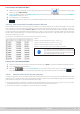
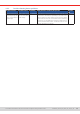

Table Of Contents
- 1. General
- 1.1 About this document
- 1.2 Warranty
- 1.3 Limitation of liability
- 1.4 Disposal of equipment
- 1.5 Product key
- 1.6 Intended usage
- 1.7 Safety
- 1.8 Technical Data
- 1.9 Construction and function
- 1.9.1 General description
- 1.9.2 Block diagram
- 1.9.3 Scope of delivery
- 1.9.4 Accessories
- 1.9.5 Options
- 1.9.6 The control panel (HMI)
- 1.9.7 USB port (rear side)
- 1.9.8 Interface module slot
- 1.9.9 Analog interface
- 1.9.10 “Share BUS” connector
- 1.9.11 “Sense” connector (remote sensing)
- 1.9.12 Master-Slave bus
- 1.9.13 Ethernet port
- 2. Installation & commissioning
- 2.1 Transport and storage
- 2.2 Unpacking and visual check
- 2.3 Installation
- 2.3.1 Safety procedures before installation and use
- 2.3.2 Preparation
- 2.3.3 Installing the device
- 2.3.4 Connection to AC supply
- 2.3.5 Connection to DC sources
- 2.3.6 Connection of remote sensing
- 2.3.7 Grounding of the DC terminal
- 2.3.8 Installation of an interface module
- 2.3.9 Connection of the analog interface
- 2.3.10 Connection of the Share bus
- 2.3.11 Connection of the USB port (rear side)
- 2.3.12 Initial commission
- 2.3.13 Commission after a firmware update or a long period of non-use
- 3. Operation and application
- 3.1 Important notes
- 3.2 Operating modes
- 3.3 Alarm conditions
- 3.4 Manual operation
- 3.5 Remote control
- 3.6 Alarms and monitoring
- 3.7 Locking the control panel (HMI)
- 3.8 Locking the adjustment limits and user profiles
- 3.9 Loading and saving user profiles
- 3.10 The function generator
- 3.10.1 Introduction
- 3.10.2 General
- 3.10.3 Method of operation
- 3.10.4 Manual operation
- 3.10.5 Sine wave function
- 3.10.6 Triangular function
- 3.10.7 Rectangular function
- 3.10.8 Trapezoidal function
- 3.10.9 DIN 40839 function
- 3.10.10 Arbitrary function
- 3.10.11 Ramp function
- 3.10.12 IU table function (XY table)
- 3.10.13 Battery test function
- 3.10.14 MPP tracking function
- 3.10.15 Remote control of the function generator
- 3.11 Other applications
- 4. Service and maintenance
- 5. Contact and support

© EA Elektro-Automatik in 2022, this information is subject to change without notice 8633200840_manual_elr_10000_2u_3kw_en_02
3.11. 2 Series connection
Series connection of electronic loads isn’t permissible and must thus not be operated! Reason: pos-
sible, asymmetrical distribution of the DC input voltage due to different internal regulation condition.
In worst case and with at least two units being wired in series connection, one unit could have a very
low internal resistance and the other a very high one which would cause the one load with the high
resistance to “see” almost the full DC input voltage which will most likely damage the DC input stage,
as well as insulation.
3.11.3 SEMI F47
SEMI F47 (the SEMI comes from semiconductor) is a specication that demands a device to continue working without in-
terruption in case of a power failure in form of an AC supply undervoltage (here: sag) of max. -50% of the rated line voltage
with a max. duration of 1.7 seconds. From rmware KE 3.02 and HMI 3.02 this has been implemented for all 10000 series
devices, but cannot be obtained by installing an update.
SEMI F47 species a voltage sag in steps with increasing voltage:
Sag of Duration at 50 Hz Duration at 60 Hz Duration in seconds
50% 10 cycles 12 cycles 0.2
30% 25 cycles 30 cycles 0.5
20% 50 cycles 60 cycles 1 s
3.11.3.1 Restrictions
• The feature will be disabled automatically and also locked if the device boots with low AC supply voltage present, i. e. 208
V (L-L) instead of the default 400 V (L-L), so it could not bridge the 1.7 s duration of the F47 pulse anymore. It means that
SEMI F47 isn’t available while derating is active.
• It requires a decreased max. power, compared to the rated power of the particular model, thus SEMI F47 is also a sort of
derating, but it’s not depending on the line voltage but what the AC input circuit (PFC) can cover without running into a power
fail. This reduced power rating is activated and deactivated together with SEMI F47
3.11.3.2 Adjustments
• SEMI F47 can either be activated/deactivated manually on the HMI (see
3.4.3.1
) or a digital interface, unless blocked due
to the current device state.
3.11.3.3 Application
The feature can be activated at any time, unless blocked to the current devices, for example when low voltage derating is
already active (see
3.2.3.1
). When activating it sometime during normal operation, the device will pop up a message after
leaving the menu, informing about the altered situation and also instantly reduce the max. available power, as well as adjust
the power set values, should the currently be higher than the new maximum. When deactivating the feature it goes vice versa,
only the power set values remain unaltered then. Due to the fact that the setting is stored beyond shutting down the device,
it could directly boot into SEMI F47 mode during next start, also showing that above mentioned pop-up once after the start
(the pop-up can be deactivated).
If later a voltage sag occurs, the level of sag or the duration decides whether the device continues its operation without switch-
ing the DC input off or if it would show a PF alarm. Without SEMI F47 being activated, the PF alarm would appear immediately
while with activated SEMI F47 it’s delayed for at least 2 seconds or will never occur. In this case, the device wouldn’t show
any reaction to the sag, nor register the occurrence in any form.