
Manual
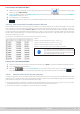
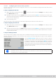
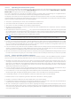
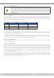
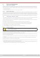

Table Of Contents
- 1. General
- 1.1 About this document
- 1.2 Warranty
- 1.3 Limitation of liability
- 1.4 Disposal of equipment
- 1.5 Product key
- 1.6 Intended usage
- 1.7 Safety
- 1.8 Technical Data
- 1.9 Construction and function
- 1.9.1 General description
- 1.9.2 Block diagram
- 1.9.3 Scope of delivery
- 1.9.4 Accessories
- 1.9.5 Options
- 1.9.6 The control panel (HMI)
- 1.9.7 USB port (rear side)
- 1.9.8 Interface module slot
- 1.9.9 Analog interface
- 1.9.10 “Share BUS” connector
- 1.9.11 “Sense” connector (remote sensing)
- 1.9.12 Master-Slave bus
- 1.9.13 Ethernet port
- 2. Installation & commissioning
- 2.1 Transport and storage
- 2.2 Unpacking and visual check
- 2.3 Installation
- 2.3.1 Safety procedures before installation and use
- 2.3.2 Preparation
- 2.3.3 Installing the device
- 2.3.4 Connection to AC supply
- 2.3.5 Connection to DC sources
- 2.3.6 Connection of remote sensing
- 2.3.7 Grounding of the DC terminal
- 2.3.8 Installation of an interface module
- 2.3.9 Connection of the analog interface
- 2.3.10 Connection of the Share bus
- 2.3.11 Connection of the USB port (rear side)
- 2.3.12 Initial commission
- 2.3.13 Commission after a firmware update or a long period of non-use
- 3. Operation and application
- 3.1 Important notes
- 3.2 Operating modes
- 3.3 Alarm conditions
- 3.4 Manual operation
- 3.5 Remote control
- 3.6 Alarms and monitoring
- 3.7 Locking the control panel (HMI)
- 3.8 Locking the adjustment limits and user profiles
- 3.9 Loading and saving user profiles
- 3.10 The function generator
- 3.10.1 Introduction
- 3.10.2 General
- 3.10.3 Method of operation
- 3.10.4 Manual operation
- 3.10.5 Sine wave function
- 3.10.6 Triangular function
- 3.10.7 Rectangular function
- 3.10.8 Trapezoidal function
- 3.10.9 DIN 40839 function
- 3.10.10 Arbitrary function
- 3.10.11 Ramp function
- 3.10.12 IU table function (XY table)
- 3.10.13 Battery test function
- 3.10.14 MPP tracking function
- 3.10.15 Remote control of the function generator
- 3.11 Other applications
- 4. Service and maintenance
- 5. Contact and support

© EA Elektro-Automatik in 2022, this information is subject to change without notice 8433200840_manual_elr_10000_2u_3kw_en_02
3.11.1.6 Conguring the master-slave operation
Now the master-slave system has to be congured on each unit. It’s recommended to congure all the slave units rst and
then the master unit.
► Step 1: Configuring all slave units
1. While the DC output is switched off, tap on in the main screen to access the Settings menu. Swipe up to nd
group Master-slave and tap it.
2. Tapping on the blue button text next to Mode will open a selector. By selecting Slave, if not already set, the master-slave
mode is activated and the device is dened as slave. Additionally, the bus termination can be activated here, if required
for the currently congured unit.
3. Leave the Settings menu.
After this, the slave is fully congured for master-slave. Repeat the procedure for all other slave units.
► Step 2: Configuring the master unit
1. While the DC output is switched off, tap on in the main screen to access the Settings menu. Swipe up to nd
group Master-slave and tap it.
2. Tapping on the blue button text next to Mode will open a selector. By selecting Master, if not already set, the master-slave
mode is activated and the device is dened as master which also automatically enable the BIAS resistor termination,
as required for the master.
► Step 3: Initializing the master
When setting a device to Master, it will instantly start to initialize the MS system and the result is displayed in the very same
window. In case the initialization is not successful or the number of units or the total power is wrong, it can be repeated in
this screen anytime.
Tapping Initialize system repeats the search for slaves in case the
detected number of slaves is less than expected, the system has been
recongured, not all slave units are already set as Slave or the cabling/
termination is still not OK. The result window shows the number of
slaves plus the total current, power and resistance of the MS system.
In case there are no slaves found at all, the master will still initialize the
MS system with only itself.
As long as MS mode remains activated, the initialization process of the master-slave system will be re-
peated each time the master unit is powered. The initialization can also be repeated manually anytime via
the Settings menu, in group “Master-Slave”.