
Manual
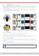
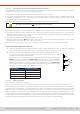
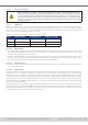

Table Of Contents
- 1. General
- 1.1 About this document
- 1.2 Warranty
- 1.3 Limitation of liability
- 1.4 Disposal of equipment
- 1.5 Product key
- 1.6 Intended usage
- 1.7 Safety
- 1.8 Technical Data
- 1.9 Construction and function
- 1.9.1 General description
- 1.9.2 Block diagram
- 1.9.3 Scope of delivery
- 1.9.4 Accessories
- 1.9.5 Options
- 1.9.6 The control panel (HMI)
- 1.9.7 USB port (rear side)
- 1.9.8 Interface module slot
- 1.9.9 Analog interface
- 1.9.10 “Share BUS” connector
- 1.9.11 “Sense” connector (remote sensing)
- 1.9.12 Master-Slave bus
- 1.9.13 Ethernet port
- 2. Installation & commissioning
- 2.1 Transport and storage
- 2.2 Unpacking and visual check
- 2.3 Installation
- 2.3.1 Safety procedures before installation and use
- 2.3.2 Preparation
- 2.3.3 Installing the device
- 2.3.4 Connection to AC supply
- 2.3.5 Connection to DC sources
- 2.3.6 Connection of remote sensing
- 2.3.7 Grounding of the DC terminal
- 2.3.8 Installation of an interface module
- 2.3.9 Connection of the analog interface
- 2.3.10 Connection of the Share bus
- 2.3.11 Connection of the USB port (rear side)
- 2.3.12 Initial commission
- 2.3.13 Commission after a firmware update or a long period of non-use
- 3. Operation and application
- 3.1 Important notes
- 3.2 Operating modes
- 3.3 Alarm conditions
- 3.4 Manual operation
- 3.5 Remote control
- 3.6 Alarms and monitoring
- 3.7 Locking the control panel (HMI)
- 3.8 Locking the adjustment limits and user profiles
- 3.9 Loading and saving user profiles
- 3.10 The function generator
- 3.10.1 Introduction
- 3.10.2 General
- 3.10.3 Method of operation
- 3.10.4 Manual operation
- 3.10.5 Sine wave function
- 3.10.6 Triangular function
- 3.10.7 Rectangular function
- 3.10.8 Trapezoidal function
- 3.10.9 DIN 40839 function
- 3.10.10 Arbitrary function
- 3.10.11 Ramp function
- 3.10.12 IU table function (XY table)
- 3.10.13 Battery test function
- 3.10.14 MPP tracking function
- 3.10.15 Remote control of the function generator
- 3.11 Other applications
- 4. Service and maintenance
- 5. Contact and support

© EA Elektro-Automatik in 2022, this information is subject to change without notice 8333200840_manual_elr_10000_2u_3kw_en_02
3.11.1.4 Wiring and set-up of the digital master-slave bus
The master-slave connectors are built-in and can be connected via network cables (≥CAT3, patch cable). After this, MS can
be congured manually or by remote control. The following applies:
• A maximum of 64 units can be connected via the bus: 1 master and up to 63 slaves.
• Connection only between devices of same kind, i.e. electronic load to electronic load; connection of different power classes
is allowed and supported, e. g. one 1.5 kW 2U with one 3 kW 2U to achieve a total of 4.5 kW, but requires to have at least
rmware KE/HMI 3.02 installed on all units
• Units at the end of the bus should be terminated, if necessary (see below for more information)
The master-slave bus must not be wired using crossover cables!
Later operation of the MS system implies:
• The master unit displays, or makes available to be read by the remote controller, the sum of the actual values of all the units
• The ranges for setting the values, adjustment limits, protections (OVP etc.) and user events (UVD etc.) of the master are
adapted to the total number of units. Thus, if e.g. 5 units each with a power of 3 kW are connected to a 15 kW system, then
the master can be set in the range 0...15 kW.
• Slaves are no operable as long as being controlled by the master
• Slave units will show the alarm MSP in the display as long as they not have been initialized by the master. The same alarm
is signaled after a connection drop to the master unit occurred.
• In case the function generator of the master unit is going to be used, the Share bus must be connected as well
► How to connect the digital master-slave bus
1. Switch off all units and connect the master-slave bus with network cables (CAT3 or better, cables not included). It
doesn’t matter which of the two master-slave sockets (RJ45, backside) is connected to the next unit.
2. Depending on the desired conguration the units are then also connected at their DC terminals.
The two units at the beginning and end of the chain must be terminated, while the master
requires a separate setting. See table below.
Termination is done with internal electronic switches which are controlled from within the
Settings menu of the device in group Master-slave. This can be done as part of setting up
every unit as master or slave, but should be done before the master is going to be set as
Master, because doing so immediately triggers a bus initialization. In group Master-Slave
the termination resistors for BIAS and the bus itself (TERM, see gure to the right) can be
set separately. Settings matrix for the units on the MS bus:
Device position Termination setting(s)
Master (at end of bus) BIAS + TERM
Master (central in bus) BIAS
Slave (at end of bus) TERM
Slave (central in bus) -
R
R
+
B
A
BIAS
BIAS
MS
Bus
R
TERM
3.11.1.5 Mixed systems
As mixed systems following is understood:
• Different power classes, like 1.5 kW, 3 kW and 15 kW within one master-slave system (requires at rmware KE 3.02)
Combining different power classes can have an unexpected side effect, such that the resulting total power, as displayed by
the master after the initialization, isn’t the expected one, but lower. This depends on what unit and power class has been
picked as master. In such a situation the golden rule is: always select the master from the units with the highest power rating.
Example: you want to connect a 30 kW unit and a 3kW unit in order to achieve 33 kW. Generally, the voltage rating must match,
but current and power rating can be different. To be precise, the power rating is decisive. When using the 3 kW unit as master,
the total system power will only be 28 kW (with a master running rmware KE 3.02), which is even less than the single 30 kW
unit. When, however, switching the master to the 30 kW unit, the system will result in 33 kW total power.