
Manual
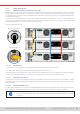
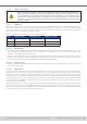

Table Of Contents
- 1. General
- 1.1 About this document
- 1.2 Warranty
- 1.3 Limitation of liability
- 1.4 Disposal of equipment
- 1.5 Product key
- 1.6 Intended usage
- 1.7 Safety
- 1.8 Technical Data
- 1.9 Construction and function
- 1.9.1 General description
- 1.9.2 Block diagram
- 1.9.3 Scope of delivery
- 1.9.4 Accessories
- 1.9.5 Options
- 1.9.6 The control panel (HMI)
- 1.9.7 USB port (rear side)
- 1.9.8 Interface module slot
- 1.9.9 Analog interface
- 1.9.10 “Share BUS” connector
- 1.9.11 “Sense” connector (remote sensing)
- 1.9.12 Master-Slave bus
- 1.9.13 Ethernet port
- 2. Installation & commissioning
- 2.1 Transport and storage
- 2.2 Unpacking and visual check
- 2.3 Installation
- 2.3.1 Safety procedures before installation and use
- 2.3.2 Preparation
- 2.3.3 Installing the device
- 2.3.4 Connection to AC supply
- 2.3.5 Connection to DC sources
- 2.3.6 Connection of remote sensing
- 2.3.7 Grounding of the DC terminal
- 2.3.8 Installation of an interface module
- 2.3.9 Connection of the analog interface
- 2.3.10 Connection of the Share bus
- 2.3.11 Connection of the USB port (rear side)
- 2.3.12 Initial commission
- 2.3.13 Commission after a firmware update or a long period of non-use
- 3. Operation and application
- 3.1 Important notes
- 3.2 Operating modes
- 3.3 Alarm conditions
- 3.4 Manual operation
- 3.5 Remote control
- 3.6 Alarms and monitoring
- 3.7 Locking the control panel (HMI)
- 3.8 Locking the adjustment limits and user profiles
- 3.9 Loading and saving user profiles
- 3.10 The function generator
- 3.10.1 Introduction
- 3.10.2 General
- 3.10.3 Method of operation
- 3.10.4 Manual operation
- 3.10.5 Sine wave function
- 3.10.6 Triangular function
- 3.10.7 Rectangular function
- 3.10.8 Trapezoidal function
- 3.10.9 DIN 40839 function
- 3.10.10 Arbitrary function
- 3.10.11 Ramp function
- 3.10.12 IU table function (XY table)
- 3.10.13 Battery test function
- 3.10.14 MPP tracking function
- 3.10.15 Remote control of the function generator
- 3.11 Other applications
- 4. Service and maintenance
- 5. Contact and support

© EA Elektro-Automatik in 2022, this information is subject to change without notice 8233200840_manual_elr_10000_2u_3kw_en_02
3.11 Other applications
3.11.1 Parallel operation in master-slave (MS)
Multiple devices of same kind can be connected in parallel in order to create a system with higher total current and hence
higher power. For parallel operation in master-slave mode the units are usually connected with their DC inputs, their Share
bus and their master-slave bus, which is a digital bus that makes the system work as one big unit regarding adjusted values,
actual values and status.
The Share bus is intended to balance the units dynamically in their voltage on the DC input, i.e. in CV mode, especially if the
master unit runs a dynamic function. In order for this bus to work correctly, at least the DC minus poles of all units have to be
connected, because DC minus is the reference for the Share bus.
Principle view without source:
Share bus connection
Master-slave bus
3.11.1.1 Restrictions
Compared to normal operation of a single device, master-slave operation has some restrictions:
• The MS system reacts partly different in alarm situations (see below in
3.11.1.8
)
• Using the Share bus makes the system react as dynamic as possible, but it’s still not as dynamic as single unit operation
• Connection to identical models from other series is not supported, the master would not initialize them
3.11.1.2 Wiring the DC inputs
The DC input of every unit in the parallel operation is connected with correct polarity to the next unit, using cables or copper
bars with a cross section according to the total system current and with short as possible length, so their inductance is as
low as possible.
3.11.1.3 Wiring the Share bus
The Share bus is wired from unit to unit with standard BNC cables (coaxial, 50 Ω type) with a length of 0.5 m (1.64 ft) or similar.
Both sockets are internally connected and are not specically input or output. The labeling is only for orientation.
•
A max. of 64 units can be connected via Share bus.
•
When connecting the Share bus before a device had been congured as Master or Slave, an SF alarm
will occur