
Manual
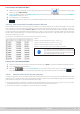
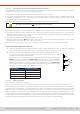
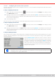
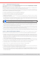
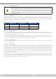

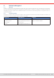

Table Of Contents
- 1. General
- 1.1 About this document
- 1.2 Warranty
- 1.3 Limitation of liability
- 1.4 Disposal of equipment
- 1.5 Product key
- 1.6 Intended usage
- 1.7 Safety
- 1.8 Technical Data
- 1.9 Construction and function
- 1.9.1 General description
- 1.9.2 Block diagram
- 1.9.3 Scope of delivery
- 1.9.4 Accessories
- 1.9.5 Options
- 1.9.6 The control panel (HMI)
- 1.9.7 USB port (rear side)
- 1.9.8 Interface module slot
- 1.9.9 Analog interface
- 1.9.10 “Share BUS” connector
- 1.9.11 “Sense” connector (remote sensing)
- 1.9.12 Master-Slave bus
- 1.9.13 Ethernet port
- 2. Installation & commissioning
- 2.1 Transport and storage
- 2.2 Unpacking and visual check
- 2.3 Installation
- 2.3.1 Safety procedures before installation and use
- 2.3.2 Preparation
- 2.3.3 Installing the device
- 2.3.4 Connection to AC supply
- 2.3.5 Connection to DC sources
- 2.3.6 Connection of remote sensing
- 2.3.7 Grounding of the DC terminal
- 2.3.8 Installation of an interface module
- 2.3.9 Connection of the analog interface
- 2.3.10 Connection of the Share bus
- 2.3.11 Connection of the USB port (rear side)
- 2.3.12 Initial commission
- 2.3.13 Commission after a firmware update or a long period of non-use
- 3. Operation and application
- 3.1 Important notes
- 3.2 Operating modes
- 3.3 Alarm conditions
- 3.4 Manual operation
- 3.5 Remote control
- 3.6 Alarms and monitoring
- 3.7 Locking the control panel (HMI)
- 3.8 Locking the adjustment limits and user profiles
- 3.9 Loading and saving user profiles
- 3.10 The function generator
- 3.10.1 Introduction
- 3.10.2 General
- 3.10.3 Method of operation
- 3.10.4 Manual operation
- 3.10.5 Sine wave function
- 3.10.6 Triangular function
- 3.10.7 Rectangular function
- 3.10.8 Trapezoidal function
- 3.10.9 DIN 40839 function
- 3.10.10 Arbitrary function
- 3.10.11 Ramp function
- 3.10.12 IU table function (XY table)
- 3.10.13 Battery test function
- 3.10.14 MPP tracking function
- 3.10.15 Remote control of the function generator
- 3.11 Other applications
- 4. Service and maintenance
- 5. Contact and support

© EA Elektro-Automatik in 2022, this information is subject to change without notice 8133200840_manual_elr_10000_2u_3kw_en_02
► How to load a curve data le for MPP4
1. While the DC input is switched off, enter the function generator by tapping on . In the selection swipe to nd
and tap on group MPP Tracking.
2. In the area “Mode selection” select MPP4 (User curve). In the lower part under Parameter a new tap eld Load MPP4
voltage values will appear. Tap it.
3. Insert USB stick, if not already done.
4. The next screen searches the stick for compatible les and lists them. Tap the one you want to load and conrm with
.
3.10.14. 6 Save result data from MPP4 mode to USB stick
After the MPP4 function has run through, the result data can be saved to USB stick. The device will always save 100 data
sets consisting of the actual values of voltage, current and power belonging to the points it has run through. There is no
extra numbering. In case the settings Start and End were not 1 and 100, the true result data can later be ltered from the le.
Points which where not adjusted are automatically set to 0 V, thus it’s very important to carefully adjust start and end point
because with a voltage setting of 0 V an electronic load would draw its rated current. That’s because in this mode, current
and power are always set to max.
Format of the result data le (for naming convention see section
1.9.6.5
):
Legend:
• Column A: actual voltage of points 1-100 (= U
MPP
)
• Column B: actual current of points 1-100 (= I
MPP
)
• Column C: actual power of points 1-100 (= P
MPP
)
• Rows 1-100: result data sets of all possible curve points
The values in the example table to the left are with
physical units. If that’s not wanted, they can be turned
off in the “General settings” of the device with param-
eter “USB logging with units (V,A,W)”.
► How to save a curve data le for MPP4
1. After the function has run through, it will stop automatically. Tap on Back to go back to the MPP4 conguration screen.
2. Insert a USB stick, if not already done.
3. Below the button tap on Save records. The next screen searches the stick for compatible les and lists
them. Either tap one to select it (overwrite) or don’t select any le to create a new le and conrm with .
3.10.15 Remote control of the function generator
The function generator can be remotely controlled, but conguration and control of the functions with individual commands
is different from manual operation. The external documentation “Programming Guide ModBus & SCPI” on the included USB
stick explains the approach. In general the following items apply:
• The function generator isn’t directly controllable via the analog interface; the only impact to the function run can come from
pin REM-SB switching the DC input off and on, which will also stop and restart the function
• The function generator is unavailable if R mode (resistance) is activated