
Manual


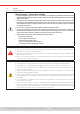
Table Of Contents
- 1. General
- 1.1 About this document
- 1.2 Warranty
- 1.3 Limitation of liability
- 1.4 Disposal of equipment
- 1.5 Product key
- 1.6 Intended usage
- 1.7 Safety
- 1.8 Technical Data
- 1.9 Construction and function
- 1.9.1 General description
- 1.9.2 Block diagram
- 1.9.3 Scope of delivery
- 1.9.4 Accessories
- 1.9.5 Options
- 1.9.6 The control panel (HMI)
- 1.9.7 USB port (rear side)
- 1.9.8 Interface module slot
- 1.9.9 Analog interface
- 1.9.10 “Share BUS” connector
- 1.9.11 “Sense” connector (remote sensing)
- 1.9.12 Master-Slave bus
- 1.9.13 Ethernet port
- 2. Installation & commissioning
- 2.1 Transport and storage
- 2.2 Unpacking and visual check
- 2.3 Installation
- 2.3.1 Safety procedures before installation and use
- 2.3.2 Preparation
- 2.3.3 Installing the device
- 2.3.4 Connection to AC supply
- 2.3.5 Connection to DC sources
- 2.3.6 Connection of remote sensing
- 2.3.7 Grounding of the DC terminal
- 2.3.8 Installation of an interface module
- 2.3.9 Connection of the analog interface
- 2.3.10 Connection of the Share bus
- 2.3.11 Connection of the USB port (rear side)
- 2.3.12 Initial commission
- 2.3.13 Commission after a firmware update or a long period of non-use
- 3. Operation and application
- 3.1 Important notes
- 3.2 Operating modes
- 3.3 Alarm conditions
- 3.4 Manual operation
- 3.5 Remote control
- 3.6 Alarms and monitoring
- 3.7 Locking the control panel (HMI)
- 3.8 Locking the adjustment limits and user profiles
- 3.9 Loading and saving user profiles
- 3.10 The function generator
- 3.10.1 Introduction
- 3.10.2 General
- 3.10.3 Method of operation
- 3.10.4 Manual operation
- 3.10.5 Sine wave function
- 3.10.6 Triangular function
- 3.10.7 Rectangular function
- 3.10.8 Trapezoidal function
- 3.10.9 DIN 40839 function
- 3.10.10 Arbitrary function
- 3.10.11 Ramp function
- 3.10.12 IU table function (XY table)
- 3.10.13 Battery test function
- 3.10.14 MPP tracking function
- 3.10.15 Remote control of the function generator
- 3.11 Other applications
- 4. Service and maintenance
- 5. Contact and support

© EA Elektro-Automatik in 2022, this information is subject to change without notice 833200840_manual_elr_10000_2u_3kw_en_02
1.7 Safety
1.7.1 Safety notices
Mortal danger - Hazardous voltage
• Electrical equipment operation means that some parts accessible on the outside of the device can be
under high voltage. Therefore all parts under voltage must be covered during operation! This basically
applies to all models.
• The DC terminal is isolated from the AC input and not connected to ground internally. Hence there can
be dangerous potential between the DC poles and PE, for instance caused by a connected external
source application. Due to charged capacitors this could even be true if the DC input or the device
are already switched off.
• Do not insert any object, particularly metallic, through the ventilator slots!
• For every reconguration on the AC or DC terminals, specically those which can have a dangerous
voltage potential, the device must be cut completely from the AC supply (main switch on the distant
end of the AC cable); it doesn’t suce to only use the power switch on the front
• Always follow 5 safety rules when working with electric devices:
• Disconnect completely
• Secure against reconnection
• Verify that the system is dead
• Carry out earthing and short-circuiting
• Provide protection from adjacent live parts
• Avoid any use of liquids near the equipment. Protect the device from wet, damp and condensation.
• Do not connect external power sources with reversed polarity to the DC terminal! The equipment will be
damaged, even when completely powered off.
• Never connect external power sources to the DC terminal that can generate a higher voltage than the
rated voltage of the device!
• Never insert a network cable which is connected to Ethernet or its components into the master-slave
sockets on the rear side of the device!
• The equipment must only be used as intended
• The equipment is only approved for use within the connection limits stated on the product label.
• ESD regulations must be applied when plugging interface cards or modules into the relative slot
• Interface cards or modules may only be attached or removed after the device is switched off. It’s not
necessary to open the device.
• Always congure the various protecting features against overcurrent, overvoltage etc. for sensitive loads
to what the target application requires!
• Always make sure that the energy recovery can feed back the inverted energy and that it does not switch
to isolated operation. For situations of isolated operation a supervision device (grid protection) has to
be installed
• It’s not allowed to run the device on AC sources such as generators or UPS equipment. It must only be
connected to a power grid!
• When controlling the device manually on the HMI while it’s connected to any controlling unit (PLC, PC
etc.) via any analog or digital interface, that controlling unit could take over remote control anytime; for
safety reasons it’s recommended to block remote control by activating the so-called local mode (also
see
“3.4. Manual operation”
and
“3.4.3. Conguration via the menu”
)