
Manual
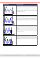
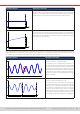
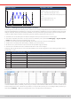

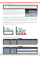
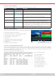

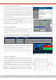
Table Of Contents
- 1. General
- 1.1 About this document
- 1.2 Warranty
- 1.3 Limitation of liability
- 1.4 Disposal of equipment
- 1.5 Product key
- 1.6 Intended usage
- 1.7 Safety
- 1.8 Technical Data
- 1.9 Construction and function
- 1.9.1 General description
- 1.9.2 Block diagram
- 1.9.3 Scope of delivery
- 1.9.4 Accessories
- 1.9.5 Options
- 1.9.6 The control panel (HMI)
- 1.9.7 USB port (rear side)
- 1.9.8 Interface module slot
- 1.9.9 Analog interface
- 1.9.10 “Share BUS” connector
- 1.9.11 “Sense” connector (remote sensing)
- 1.9.12 Master-Slave bus
- 1.9.13 Ethernet port
- 2. Installation & commissioning
- 2.1 Transport and storage
- 2.2 Unpacking and visual check
- 2.3 Installation
- 2.3.1 Safety procedures before installation and use
- 2.3.2 Preparation
- 2.3.3 Installing the device
- 2.3.4 Connection to AC supply
- 2.3.5 Connection to DC sources
- 2.3.6 Connection of remote sensing
- 2.3.7 Grounding of the DC terminal
- 2.3.8 Installation of an interface module
- 2.3.9 Connection of the analog interface
- 2.3.10 Connection of the Share bus
- 2.3.11 Connection of the USB port (rear side)
- 2.3.12 Initial commission
- 2.3.13 Commission after a firmware update or a long period of non-use
- 3. Operation and application
- 3.1 Important notes
- 3.2 Operating modes
- 3.3 Alarm conditions
- 3.4 Manual operation
- 3.5 Remote control
- 3.6 Alarms and monitoring
- 3.7 Locking the control panel (HMI)
- 3.8 Locking the adjustment limits and user profiles
- 3.9 Loading and saving user profiles
- 3.10 The function generator
- 3.10.1 Introduction
- 3.10.2 General
- 3.10.3 Method of operation
- 3.10.4 Manual operation
- 3.10.5 Sine wave function
- 3.10.6 Triangular function
- 3.10.7 Rectangular function
- 3.10.8 Trapezoidal function
- 3.10.9 DIN 40839 function
- 3.10.10 Arbitrary function
- 3.10.11 Ramp function
- 3.10.12 IU table function (XY table)
- 3.10.13 Battery test function
- 3.10.14 MPP tracking function
- 3.10.15 Remote control of the function generator
- 3.11 Other applications
- 4. Service and maintenance
- 5. Contact and support

© EA Elektro-Automatik in 2022, this information is subject to change without notice 7933200840_manual_elr_10000_2u_3kw_en_02
3.10.14 MPP tracking function
MPP stands for the maximum power point (see principle view to the right)
on the power curve of solar panels. Solar inverters, when connected to
such panels, constantly track this MPP once it has been found.
An electronic load can easily imitate this behavior and hence be used to
test even huge solar panels without having to connect a usually big solar
inverter device which also requires to have a load connected to its AC
output. Furthermore, all MPP tracking related parameters of the electronic
load can be adjusted and it’s thus more exible than an inverter with its
limited DC input range.
For evaluation and analysis purposes, the device can also record measured
data, i. e. DC input values such as actual voltage, current or power, to USB
stick or provide them for reading via digital interface.
The MPP tracking function offers four modes. Unlike with the manual
handling of other functions, values for the MPP tracking are only entered
by direct input via the touch screen.
3.10.14.1 Mode MPP1
This mode is also called “Find MPP”. It’s the simplest option to have the
device nd the MPP of a connected solar panel. It requires to set only
three parameters. Value U
OC
is necessary, because it helps to
MPP
Power
Voltage
nd the MPP quicker as if the device would start at 0 V or maximum voltage. Actually, it would start at a voltage level slightly
above U
OC
.
I
SC
is used as a upper limit for the current, so the device would not try to draw more current than the panel is specied for.
Following parameters can be congured for tracking mode MPP1:
Value Range Description
U
OC
(open circuit voltage) 0...U
Nom
Voltage of the unloaded solar panel, taken from the panel specs
I
SC
(short-circuit current) 0...I
Nom
Short-circuit current, taken from the panel specs
Tracking interval (Δt) 5...60000 ms Time between two tracking attempts when nding the MPP
Application and result:
After the three parameters have been set, the function can be started. As
soon as the MPP has been found, the function will stop and switch off the
DC input. The acquired MPP values of voltage (U
MPP
), current (I
MPP
) and
power (P
MPP
) would then be shown in the display.
The time of a function run depends on the parameter Δt. Even with the
minimum setting of 5 ms one run usually takes already a few seconds.
3.10.14. 2 Mode MPP2
This mode tracks the MPP, so it’s closest to the operation of a real solar
inverter. Once the MPP is found, the function won’t stop, but try to track the
MPP permanently. Due to the nature of solar panels this can only be done
below the level of the MPP. As soon as this point is reached, the voltage
starts to sink further and so does the actual power. The additional param-
eter Delta P denes how much the power may fall before the direction
is reversed and the voltage starts to rise again until the load reaches the
MPP. The result are zigzag shaped curves of both, voltage and current.
Typical curves are shown in the picture to the right. For the example the
Delta P was set to a quite small value, so the power curve looks almost
linear. With a small Delta P the load would always track close to the MPP.