
Manual
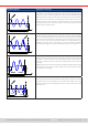
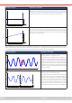
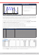

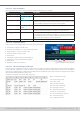

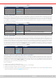
Table Of Contents
- 1. General
- 1.1 About this document
- 1.2 Warranty
- 1.3 Limitation of liability
- 1.4 Disposal of equipment
- 1.5 Product key
- 1.6 Intended usage
- 1.7 Safety
- 1.8 Technical Data
- 1.9 Construction and function
- 1.9.1 General description
- 1.9.2 Block diagram
- 1.9.3 Scope of delivery
- 1.9.4 Accessories
- 1.9.5 Options
- 1.9.6 The control panel (HMI)
- 1.9.7 USB port (rear side)
- 1.9.8 Interface module slot
- 1.9.9 Analog interface
- 1.9.10 “Share BUS” connector
- 1.9.11 “Sense” connector (remote sensing)
- 1.9.12 Master-Slave bus
- 1.9.13 Ethernet port
- 2. Installation & commissioning
- 2.1 Transport and storage
- 2.2 Unpacking and visual check
- 2.3 Installation
- 2.3.1 Safety procedures before installation and use
- 2.3.2 Preparation
- 2.3.3 Installing the device
- 2.3.4 Connection to AC supply
- 2.3.5 Connection to DC sources
- 2.3.6 Connection of remote sensing
- 2.3.7 Grounding of the DC terminal
- 2.3.8 Installation of an interface module
- 2.3.9 Connection of the analog interface
- 2.3.10 Connection of the Share bus
- 2.3.11 Connection of the USB port (rear side)
- 2.3.12 Initial commission
- 2.3.13 Commission after a firmware update or a long period of non-use
- 3. Operation and application
- 3.1 Important notes
- 3.2 Operating modes
- 3.3 Alarm conditions
- 3.4 Manual operation
- 3.5 Remote control
- 3.6 Alarms and monitoring
- 3.7 Locking the control panel (HMI)
- 3.8 Locking the adjustment limits and user profiles
- 3.9 Loading and saving user profiles
- 3.10 The function generator
- 3.10.1 Introduction
- 3.10.2 General
- 3.10.3 Method of operation
- 3.10.4 Manual operation
- 3.10.5 Sine wave function
- 3.10.6 Triangular function
- 3.10.7 Rectangular function
- 3.10.8 Trapezoidal function
- 3.10.9 DIN 40839 function
- 3.10.10 Arbitrary function
- 3.10.11 Ramp function
- 3.10.12 IU table function (XY table)
- 3.10.13 Battery test function
- 3.10.14 MPP tracking function
- 3.10.15 Remote control of the function generator
- 3.11 Other applications
- 4. Service and maintenance
- 5. Contact and support

© EA Elektro-Automatik in 2022, this information is subject to change without notice 7733200840_manual_elr_10000_2u_3kw_en_02
3.10.13.3 Stop conditions
These parameters are valid for all test modes and dene additionally stop conditions:
Value Range Description
Discharge end voltage 0 V...U
Nom
Threshold (in Volt) to stop discharging (only for discharge modes)
Action: Ah limit None, Signal, End
of test
Enables the optional stop condition
Discharge capacity 0...99999.99 Ah Threshold for the max. capacity to consume from or feed to the battery
and after which the test can stop automatically. This is optional, so that
also more battery capacity can be consumed or supplied.
Action: Time limit None, Signal, End
of test
Enables the optional stop condition
Discharge time 00:00:00...10:00:00 h Test time after which the test can stop automatically. This stop criteria is
optional, it means that single tests can also run longer than 10 h.
USB logging on/off By setting the check mark, USB logging is enabled and will record data
on a properly formatted USB stick, if plugged in to the front USB port. The
recorded data differs from the USB log data recorded during “normal” USB
logging in all other operation modes of the device.
Logging interval 100 ms - 1 s, 5 s, 10 s Writing interval for USB logging
3.10.13 . 4 Displayed values
During the test run, the display will show various values and statuses:
• Actual battery voltage on the DC input
• Discharge end voltage U
DV
in V (only in discharge mode)
• Charge voltage in V (only in charge mode)
• Actual discharge or charge current
• Actual power
• Total battery capacity (charging & discharging)
• Total battery energy (charging & discharging)
• Elapsed time
• Regulation mode (CC, CP, CR, CV)
Figure 15 - Example from static discharge
3.10.13 . 5 Data recording to USB stick
At the end of the conguration of all test modes there is the option to enable a logging feature. With a USB stick plugged
and formatted as required (see
1.9.6.5
), the device can record data during the test run directly to the stick and in the dened
interval. Active USB logging is indicated in the display with a small diskette symbol. After the test has stopped, the recorded
data will be available as text le in CSV format.
Log le format example from static discharge mode:
Static = Selected test mode
Iset = Discharging current
Pset = Max. power
Rset = Desired resistance
DV = Discharge end voltage
DT = Discharge end time
DC = Discharge end capacity
U/I/Pactual = Actual values
Ah = Consumed battery capacity
Wh = Consumed energy
Time = Elapsed test time