
Manual
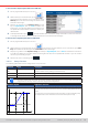

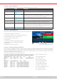

Table Of Contents
- 1. General
- 1.1 About this document
- 1.2 Warranty
- 1.3 Limitation of liability
- 1.4 Disposal of equipment
- 1.5 Product key
- 1.6 Intended usage
- 1.7 Safety
- 1.8 Technical Data
- 1.9 Construction and function
- 1.9.1 General description
- 1.9.2 Block diagram
- 1.9.3 Scope of delivery
- 1.9.4 Accessories
- 1.9.5 Options
- 1.9.6 The control panel (HMI)
- 1.9.7 USB port (rear side)
- 1.9.8 Interface module slot
- 1.9.9 Analog interface
- 1.9.10 “Share BUS” connector
- 1.9.11 “Sense” connector (remote sensing)
- 1.9.12 Master-Slave bus
- 1.9.13 Ethernet port
- 2. Installation & commissioning
- 2.1 Transport and storage
- 2.2 Unpacking and visual check
- 2.3 Installation
- 2.3.1 Safety procedures before installation and use
- 2.3.2 Preparation
- 2.3.3 Installing the device
- 2.3.4 Connection to AC supply
- 2.3.5 Connection to DC sources
- 2.3.6 Connection of remote sensing
- 2.3.7 Grounding of the DC terminal
- 2.3.8 Installation of an interface module
- 2.3.9 Connection of the analog interface
- 2.3.10 Connection of the Share bus
- 2.3.11 Connection of the USB port (rear side)
- 2.3.12 Initial commission
- 2.3.13 Commission after a firmware update or a long period of non-use
- 3. Operation and application
- 3.1 Important notes
- 3.2 Operating modes
- 3.3 Alarm conditions
- 3.4 Manual operation
- 3.5 Remote control
- 3.6 Alarms and monitoring
- 3.7 Locking the control panel (HMI)
- 3.8 Locking the adjustment limits and user profiles
- 3.9 Loading and saving user profiles
- 3.10 The function generator
- 3.10.1 Introduction
- 3.10.2 General
- 3.10.3 Method of operation
- 3.10.4 Manual operation
- 3.10.5 Sine wave function
- 3.10.6 Triangular function
- 3.10.7 Rectangular function
- 3.10.8 Trapezoidal function
- 3.10.9 DIN 40839 function
- 3.10.10 Arbitrary function
- 3.10.11 Ramp function
- 3.10.12 IU table function (XY table)
- 3.10.13 Battery test function
- 3.10.14 MPP tracking function
- 3.10.15 Remote control of the function generator
- 3.11 Other applications
- 4. Service and maintenance
- 5. Contact and support

© EA Elektro-Automatik in 2022, this information is subject to change without notice 7533200840_manual_elr_10000_2u_3kw_en_02
3.10.12 IU table function (XY table)
The IU function offer the user the possibility to set a DC input current dependent on the DC input voltage. The function is table
driven with exactly 4096 values, which are distributed over the whole measured range of actual input voltage in the range of
0...125% Unom, of which only 0...102% are effective . The table can either be uploaded from an USB stick through the front
side USB port of the device or via remote control (ModBus RTU protocol or SCPI). The functions are:
IU function: I = f(U)
In the IU function, an internal measuring circuit measures the voltage on the DC input. For every possible actual voltage on
the scale of 0...125% the loaded IU table holds a current value, which can be any value between 0 and rated current. The values
uploaded from an USB stick will always be interpreted as current values even if the user calculated them as voltage values
and loaded them as an IU table due to wrong le naming.
Uploading of a table from an USB stick must use text les in CSV format (*.csv). Plausibility is checked
when loading, i.e. values not too high, number of values correct etc. which may abort loading when errors
are found.
The 4096 values in the table are only checked for size and count. If all the values were to be graphically
plotted into a curve it could include huge step changes in the current. This could lead to complications
for the connected source if, for example, the internal voltage measurement swings slightly so that
the current jumps back and forth between a few values in the table which, in the worst case, could be
bounce between 0 A and the maximum current.
3.10.12 .1 Loading IU tables from USB stick
The so-called IU tables can be loaded from a le via a standard
USB stick that is formatted in FAT32. In order to load the le, it
has to meet following specications:
• The le name always begins with IU (not case-sensitive)
• The le must be a text le of type Excel CSV and must only
contain one column with exactly 4096 values without gaps
• Values with decimal places must use decimal separator that
matches the selection in the general setting Log le separator
format, which also denes the decimal separator between dot
and comma (US default should be dot)
• No value may exceed the rated current of the device model. For example, if you have a 420 A model, none of the 4096 values
must be higher than 420 A (the adjustment limits from the device’s front panel do not apply here)
• The le(s) has/have to be put inside a folder named HMI_FILES in the root path of the stick
If these specications are not met, the device won’t accept the le and put out an error message in the display. The USB stick
may contain multiple IU les with different names and list them for the selection of one.
► How to load an IU table from a USB stick:
1. While the DC input is switched off, open the function selection menu by tapping on , then select group XY table.
2. Insert the USB stick, if not already done, then tap on Import table and in the le selector coming up select the table you
want to load and conrm with . In case the le isn’t accepted for any of the above listed reasons, correct the
le format and content, then try again.
3. Tap to proceed to the next screen where you can adjust the global set values.
4. Finally proceed to the main function screen with , to start and control the function (also see
“3.10.4.1.
Function selection and control”).