
Manual
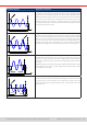
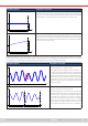
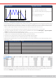
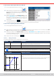

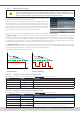
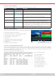

Table Of Contents
- 1. General
- 1.1 About this document
- 1.2 Warranty
- 1.3 Limitation of liability
- 1.4 Disposal of equipment
- 1.5 Product key
- 1.6 Intended usage
- 1.7 Safety
- 1.8 Technical Data
- 1.9 Construction and function
- 1.9.1 General description
- 1.9.2 Block diagram
- 1.9.3 Scope of delivery
- 1.9.4 Accessories
- 1.9.5 Options
- 1.9.6 The control panel (HMI)
- 1.9.7 USB port (rear side)
- 1.9.8 Interface module slot
- 1.9.9 Analog interface
- 1.9.10 “Share BUS” connector
- 1.9.11 “Sense” connector (remote sensing)
- 1.9.12 Master-Slave bus
- 1.9.13 Ethernet port
- 2. Installation & commissioning
- 2.1 Transport and storage
- 2.2 Unpacking and visual check
- 2.3 Installation
- 2.3.1 Safety procedures before installation and use
- 2.3.2 Preparation
- 2.3.3 Installing the device
- 2.3.4 Connection to AC supply
- 2.3.5 Connection to DC sources
- 2.3.6 Connection of remote sensing
- 2.3.7 Grounding of the DC terminal
- 2.3.8 Installation of an interface module
- 2.3.9 Connection of the analog interface
- 2.3.10 Connection of the Share bus
- 2.3.11 Connection of the USB port (rear side)
- 2.3.12 Initial commission
- 2.3.13 Commission after a firmware update or a long period of non-use
- 3. Operation and application
- 3.1 Important notes
- 3.2 Operating modes
- 3.3 Alarm conditions
- 3.4 Manual operation
- 3.5 Remote control
- 3.6 Alarms and monitoring
- 3.7 Locking the control panel (HMI)
- 3.8 Locking the adjustment limits and user profiles
- 3.9 Loading and saving user profiles
- 3.10 The function generator
- 3.10.1 Introduction
- 3.10.2 General
- 3.10.3 Method of operation
- 3.10.4 Manual operation
- 3.10.5 Sine wave function
- 3.10.6 Triangular function
- 3.10.7 Rectangular function
- 3.10.8 Trapezoidal function
- 3.10.9 DIN 40839 function
- 3.10.10 Arbitrary function
- 3.10.11 Ramp function
- 3.10.12 IU table function (XY table)
- 3.10.13 Battery test function
- 3.10.14 MPP tracking function
- 3.10.15 Remote control of the function generator
- 3.11 Other applications
- 4. Service and maintenance
- 5. Contact and support

© EA Elektro-Automatik in 2022, this information is subject to change without notice 7433200840_manual_elr_10000_2u_3kw_en_02
► How to load a sequence point table from a USB stick:
1. Do not plug the USB stick yet or remove it.
2. While the DC input is switched off, tap on to
access the function selection menu. There tap on group
Arbitrary which will show the settings as shown in the
screenshot to the right.
3. Swipe up to go down to the Sequence setup part and
tap on Import/Export, then on Load and follow the
instructions. If the le open dialog can at least list one
compatible le, it will be listed for selection. Select your
desired table.
4. To nally load the le, tap on . The selected le is then checked for validity and loaded. In case of format errors,
a message will be shown on screen. The le would have to be checked and tried again.
► How to save a sequence point table to a USB stick:
1. Do not plug the USB stick yet or remove it.
2. While the DC input is switched off, tap on to access the function selection menu. There tap on group Arbi-
trary which will show the settings as shown in the screenshot to the right.
3. Swipe up to go down to the Sequence setup part and tap on Import/Export, then on Save and follow the instructions.
In the le open dialog you can either select an existing le, if at least one compatible le is listed, or you can create a
new one by not selecting any le.
4. Save the le, new or overwriting, with .
3.10.11 Ramp function
The following parameters can be congured for a ramp function:
Parameter Range Description
Start
End
0...U
Nom
or 0...I
Nom
Start/end point of the ramp. Both values can be equal or different, which then
results in either a rising, falling or horizontal ramp
Time t1 0.1 ms...36,000,000 ms Time before ramp-up or ramp-down of the signal.
Time t2 0.1 ms...36,000,000 ms Ramp-up or ramp-down time
10 h after reaching the ramp end, the function will stop automatically (i.e. I = 0 A, in case the ramp was
assigned to the current), unless it has been stopped manually before.
Schematic diagram: Application and result:
U(I)start
t
U,I
t1 t2
U(I)End
This function generates a rising, falling or horizontally running ramp between
the start and end values over time t2. Time t1 creates a delay before the ramp
starts.
The function runs once and stops at the end value. To have a repeating ramp,
the Trapezoid function would have to be used instead (see
3.10.8
).