
Manual
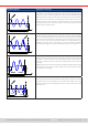
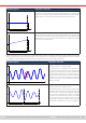
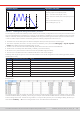

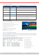

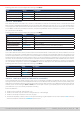
Table Of Contents
- 1. General
- 1.1 About this document
- 1.2 Warranty
- 1.3 Limitation of liability
- 1.4 Disposal of equipment
- 1.5 Product key
- 1.6 Intended usage
- 1.7 Safety
- 1.8 Technical Data
- 1.9 Construction and function
- 1.9.1 General description
- 1.9.2 Block diagram
- 1.9.3 Scope of delivery
- 1.9.4 Accessories
- 1.9.5 Options
- 1.9.6 The control panel (HMI)
- 1.9.7 USB port (rear side)
- 1.9.8 Interface module slot
- 1.9.9 Analog interface
- 1.9.10 “Share BUS” connector
- 1.9.11 “Sense” connector (remote sensing)
- 1.9.12 Master-Slave bus
- 1.9.13 Ethernet port
- 2. Installation & commissioning
- 2.1 Transport and storage
- 2.2 Unpacking and visual check
- 2.3 Installation
- 2.3.1 Safety procedures before installation and use
- 2.3.2 Preparation
- 2.3.3 Installing the device
- 2.3.4 Connection to AC supply
- 2.3.5 Connection to DC sources
- 2.3.6 Connection of remote sensing
- 2.3.7 Grounding of the DC terminal
- 2.3.8 Installation of an interface module
- 2.3.9 Connection of the analog interface
- 2.3.10 Connection of the Share bus
- 2.3.11 Connection of the USB port (rear side)
- 2.3.12 Initial commission
- 2.3.13 Commission after a firmware update or a long period of non-use
- 3. Operation and application
- 3.1 Important notes
- 3.2 Operating modes
- 3.3 Alarm conditions
- 3.4 Manual operation
- 3.5 Remote control
- 3.6 Alarms and monitoring
- 3.7 Locking the control panel (HMI)
- 3.8 Locking the adjustment limits and user profiles
- 3.9 Loading and saving user profiles
- 3.10 The function generator
- 3.10.1 Introduction
- 3.10.2 General
- 3.10.3 Method of operation
- 3.10.4 Manual operation
- 3.10.5 Sine wave function
- 3.10.6 Triangular function
- 3.10.7 Rectangular function
- 3.10.8 Trapezoidal function
- 3.10.9 DIN 40839 function
- 3.10.10 Arbitrary function
- 3.10.11 Ramp function
- 3.10.12 IU table function (XY table)
- 3.10.13 Battery test function
- 3.10.14 MPP tracking function
- 3.10.15 Remote control of the function generator
- 3.11 Other applications
- 4. Service and maintenance
- 5. Contact and support

© EA Elektro-Automatik in 2022, this information is subject to change without notice 7233200840_manual_elr_10000_2u_3kw_en_02
Schematic diagram: Applications and results:
Start (DC)
t
U,I
Seq.time
End ( DC)
Example 5: Focusing 1 cycle of 1 sequence point:
Similar to example 1 but with a start and end frequency of 0 Hz. Without a
frequency, no sine wave part (AC) will be generated and only the DC settings
will be effective. A ramp with a horizontal progression would result.
Start (DC)
t
U,I
Seq.time
End ( DC)
Example 6: Focusing 1 cycle of 1 sequence point:
Similar to example 1 but with a start and end frequency of 0 Hz. Without a
frequency no sine wave part (AC) will be generated and only the DC settings
will be effective. Here the DC start and end values are unequal and a steadily
increasing ramp would result.
By linking together a number of differently congured sequence points, complex progressions can be created. Smart cong-
uration of the arbitrary generator can be used to match triangular, sine, rectangular or trapezoidal wave functions and thus,
e.g. a sequence of rectangular waves with differing amplitudes or duty cycles could be produced.
Schematic diagram: Applications and results:
t
U,I
t
U,I
Example 7
Focusing 2 cycles of 1 sequence point:
One sequence point, congured as in example 3, is
run. Since the settings dene that the end offset (DC)
is higher than the start, the second run will revert to
the same start level as the rst, regardless of the sig-
nal level at the end of the rst run. This can produce
a discontinuity in the total progression (marked in
red) which may only be compensated with a careful
choice of settings.
t
U,I
Po int 1 Po int 2
Example 8
Focusing 1 cycle of 2 sequence points:
Two sequence points run consecutively. The rst one
generates a sine wave with increasing amplitude, the
second one with a decreasing amplitude. Together
they produce a progression as shown to the left.
In order to ensure that the wave peak in the middle
occurs only once, the rst sequence point must end
with a positive half wave and the second one start
with a negative half wave as shown in the diagram.