
Manual
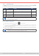
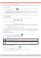

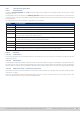
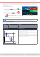
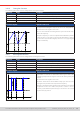
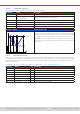
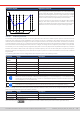
Table Of Contents
- 1. General
- 1.1 About this document
- 1.2 Warranty
- 1.3 Limitation of liability
- 1.4 Disposal of equipment
- 1.5 Product key
- 1.6 Intended usage
- 1.7 Safety
- 1.8 Technical Data
- 1.9 Construction and function
- 1.9.1 General description
- 1.9.2 Block diagram
- 1.9.3 Scope of delivery
- 1.9.4 Accessories
- 1.9.5 Options
- 1.9.6 The control panel (HMI)
- 1.9.7 USB port (rear side)
- 1.9.8 Interface module slot
- 1.9.9 Analog interface
- 1.9.10 “Share BUS” connector
- 1.9.11 “Sense” connector (remote sensing)
- 1.9.12 Master-Slave bus
- 1.9.13 Ethernet port
- 2. Installation & commissioning
- 2.1 Transport and storage
- 2.2 Unpacking and visual check
- 2.3 Installation
- 2.3.1 Safety procedures before installation and use
- 2.3.2 Preparation
- 2.3.3 Installing the device
- 2.3.4 Connection to AC supply
- 2.3.5 Connection to DC sources
- 2.3.6 Connection of remote sensing
- 2.3.7 Grounding of the DC terminal
- 2.3.8 Installation of an interface module
- 2.3.9 Connection of the analog interface
- 2.3.10 Connection of the Share bus
- 2.3.11 Connection of the USB port (rear side)
- 2.3.12 Initial commission
- 2.3.13 Commission after a firmware update or a long period of non-use
- 3. Operation and application
- 3.1 Important notes
- 3.2 Operating modes
- 3.3 Alarm conditions
- 3.4 Manual operation
- 3.5 Remote control
- 3.6 Alarms and monitoring
- 3.7 Locking the control panel (HMI)
- 3.8 Locking the adjustment limits and user profiles
- 3.9 Loading and saving user profiles
- 3.10 The function generator
- 3.10.1 Introduction
- 3.10.2 General
- 3.10.3 Method of operation
- 3.10.4 Manual operation
- 3.10.5 Sine wave function
- 3.10.6 Triangular function
- 3.10.7 Rectangular function
- 3.10.8 Trapezoidal function
- 3.10.9 DIN 40839 function
- 3.10.10 Arbitrary function
- 3.10.11 Ramp function
- 3.10.12 IU table function (XY table)
- 3.10.13 Battery test function
- 3.10.14 MPP tracking function
- 3.10.15 Remote control of the function generator
- 3.11 Other applications
- 4. Service and maintenance
- 5. Contact and support

© EA Elektro-Automatik in 2022, this information is subject to change without notice 7033200840_manual_elr_10000_2u_3kw_en_02
Schematic diagram: Application and result:
t
U
U start
1 2 3 4 5 t1
Sequence points
The function’s primary use is to load a source, for instance a
power supply, which cannot generate the curve itself and would
supply a static DC voltage. The load acts as a sink for the rapid
fall of the output voltage of the power supply enabling the voltage
progress to follow the DIN curve. The only requirement for the
source is that it features (an adjustable) current limitation.
The curve conforms to test impulse 4 of the DIN. With suitable
settings, other test impulses can be simulated. If the curve in
sequence 4 should be a sine wave, then these 5 sequence points
would have to be reconstructed using the arbitrary generator.
3.10.10 Arbitrary function
The arbitrary (freely denable) function or function generator offers the user a wider scope of options. There are 99 curve
segments (here: sequence points) available for use on either current (I) or voltage (U), all of which have the same set of pa-
rameters but can be differently congured, so that a complex function curve can be “constructed”. An arbitrary number out
of the 99 sequence points can run in a sequence point block and this block can then be repeated up to 999 times or innitely.
Since the function must be assigned to either current or voltage, mix assignments of sequence point to both is not possible.
The arbitrary curve can overlay a linear progression (DC) with a sine curve (AC) whose amplitude and frequency is shaped
between start and end. When both, start frequency and end frequency, are 0 Hz the AC overlay has no impact and only the
DC part is effective. Each sequence point is allocated a sequence point time in which the AC/DC curve from start to end will
be generated.
The following parameters can be congured for each sequence point in the arbitrary function:
Parameter Range Description
AC start
AC end
-50%...+50% I
Nom
or 0%...50% U
Nom
Start and end amplitude of the sinusoidal AC part
DC start ±(AC start...(rated value - AC start)) Start level (offset) of the DC part
DC end ±(AC end...(rated value - AC end)) End level (offset) of the DC part
Start frequency 0 Hz...10000 Hz Start frequency of the sinusoidal AC part
End frequency 0 Hz...10000 Hz End frequency of the sinusoidal AC part
Angle 0°...359° Start angle of the sinusoidal AC part
Time 0.1 ms...36,000,000 ms Time setting for the selected sequence point
The sequence point time (“Time”) and the start and end frequency are related. The minimum value for
Δf/s is 9.3. Thus, for example, a setting of start frequency = 1 Hz, end frequency = 11 Hz and time = 5 s
would not be accepted as Δf/s is only 2. A time of 1 s would be accepted or, if the time remains at 5 s, then
an end frequency = 51 Hz must be set.
The amplitude change between start and end is related to the sequence time. A minimal change over an
extended time is not possible and in such a case the device will report an inapplicable setting.
After the settings for the selected sequence point have been dened, further points can be congured. Further down below
there are some global settings for the arbitrary function:
Parameter Range Description
Cycles 0 / 1...999 Number of cycles to run the sequence point block (0 = innite)
Start sequence 1...End sequence First sequence point in the block
End sequence Start sequence...99 Last sequence point in the block
After continuing with there are global set values to dene as last part of the function generator setup.