
Manual
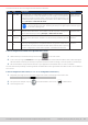
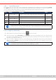
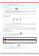

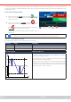
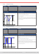
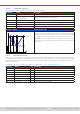
Table Of Contents
- 1. General
- 1.1 About this document
- 1.2 Warranty
- 1.3 Limitation of liability
- 1.4 Disposal of equipment
- 1.5 Product key
- 1.6 Intended usage
- 1.7 Safety
- 1.8 Technical Data
- 1.9 Construction and function
- 1.9.1 General description
- 1.9.2 Block diagram
- 1.9.3 Scope of delivery
- 1.9.4 Accessories
- 1.9.5 Options
- 1.9.6 The control panel (HMI)
- 1.9.7 USB port (rear side)
- 1.9.8 Interface module slot
- 1.9.9 Analog interface
- 1.9.10 “Share BUS” connector
- 1.9.11 “Sense” connector (remote sensing)
- 1.9.12 Master-Slave bus
- 1.9.13 Ethernet port
- 2. Installation & commissioning
- 2.1 Transport and storage
- 2.2 Unpacking and visual check
- 2.3 Installation
- 2.3.1 Safety procedures before installation and use
- 2.3.2 Preparation
- 2.3.3 Installing the device
- 2.3.4 Connection to AC supply
- 2.3.5 Connection to DC sources
- 2.3.6 Connection of remote sensing
- 2.3.7 Grounding of the DC terminal
- 2.3.8 Installation of an interface module
- 2.3.9 Connection of the analog interface
- 2.3.10 Connection of the Share bus
- 2.3.11 Connection of the USB port (rear side)
- 2.3.12 Initial commission
- 2.3.13 Commission after a firmware update or a long period of non-use
- 3. Operation and application
- 3.1 Important notes
- 3.2 Operating modes
- 3.3 Alarm conditions
- 3.4 Manual operation
- 3.5 Remote control
- 3.6 Alarms and monitoring
- 3.7 Locking the control panel (HMI)
- 3.8 Locking the adjustment limits and user profiles
- 3.9 Loading and saving user profiles
- 3.10 The function generator
- 3.10.1 Introduction
- 3.10.2 General
- 3.10.3 Method of operation
- 3.10.4 Manual operation
- 3.10.5 Sine wave function
- 3.10.6 Triangular function
- 3.10.7 Rectangular function
- 3.10.8 Trapezoidal function
- 3.10.9 DIN 40839 function
- 3.10.10 Arbitrary function
- 3.10.11 Ramp function
- 3.10.12 IU table function (XY table)
- 3.10.13 Battery test function
- 3.10.14 MPP tracking function
- 3.10.15 Remote control of the function generator
- 3.11 Other applications
- 4. Service and maintenance
- 5. Contact and support

© EA Elektro-Automatik in 2022, this information is subject to change without notice 6933200840_manual_elr_10000_2u_3kw_en_02
3.10. 8 Trapezoidal function
The following parameters can be congured for a trapezoidal function:
Parameter Range Description
Amplitude (A) 0...(rated value of U or I - |offset|) Amplitude of the signal to be generated
Offset (O) 0... (UNom - Amplitude) or 0...
(INom - Amplitude)
Offset, based on the foot of the trapezium
Time t1 0.1 ms...36,000,000 ms Time for the positive slope of the trapezoidal wave signal.
Time t2 0.1 ms...36,000,000 ms Time for the top value of the trapezoidal wave signal.
Time t3 0.1 ms...36,000,000 ms Time for the negative slope of the trapezoidal wave signal.
Time t4 0.1 ms...36,000,000 ms Time for the base value (=offset) of the trapezoidal wave signal
Schematic diagram: Application and result:
Offset
t
U,I
Amplitude
t1t2 t3 t4
Offset
t
U,I
Amplitude
t1t2 t3 t4
Same as with other functions the generated signal can be applied to the
set value of voltage (U mode) or to the current (I mode). The slopes of the
trapezium can be varied by adjusting the times for rise and fall separately.
The periodic duration and repetition frequency are the result of the four
adjustable time values. With suitable settings the trapezium can be
deformed to two triangular or two rectangular pulses. It has, therefore,
universal use.
3.10.9 DIN 40839 function
This function is based on the curve dened in DIN 40839 / EN ISO 7637 (test impulse 4), and is only applicable to voltage.
It shall replicate the progress of automobile battery voltage during engine starting. The curve is divided into 5 parts (see
diagram below) which each have the same parameters. The standard values from the DIN are set already as default values
for the ve sequences.
The following parameters can be congured for the single sequence points or the entire function:
Parameter Range Seq Description
Start 0...U
Nom
1-5 Start voltage of the ramp in part 1-5 (sequence point)
Uend 0...U
Nom
1-5 End voltage of the ramp in part 1-5 (sequence point)
Time 0.1 ms...36,000,000 ms 1-5 Time of the ramp
Cycles 0 / 1...999 - Number of times to run the entire curve (0 = infinite)
Time t1 0.1 ms...36,000,000 ms - Time after cycle before repetition (cycle <> 1)
U(Start/End) 0...U
Nom
- Voltage setting before and after the function run
I/P 0...I
Nom
/P
Nom
- Set values of current and power