
Manual
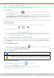

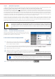
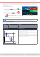
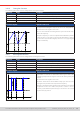
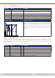
Table Of Contents
- 1. General
- 1.1 About this document
- 1.2 Warranty
- 1.3 Limitation of liability
- 1.4 Disposal of equipment
- 1.5 Product key
- 1.6 Intended usage
- 1.7 Safety
- 1.8 Technical Data
- 1.9 Construction and function
- 1.9.1 General description
- 1.9.2 Block diagram
- 1.9.3 Scope of delivery
- 1.9.4 Accessories
- 1.9.5 Options
- 1.9.6 The control panel (HMI)
- 1.9.7 USB port (rear side)
- 1.9.8 Interface module slot
- 1.9.9 Analog interface
- 1.9.10 “Share BUS” connector
- 1.9.11 “Sense” connector (remote sensing)
- 1.9.12 Master-Slave bus
- 1.9.13 Ethernet port
- 2. Installation & commissioning
- 2.1 Transport and storage
- 2.2 Unpacking and visual check
- 2.3 Installation
- 2.3.1 Safety procedures before installation and use
- 2.3.2 Preparation
- 2.3.3 Installing the device
- 2.3.4 Connection to AC supply
- 2.3.5 Connection to DC sources
- 2.3.6 Connection of remote sensing
- 2.3.7 Grounding of the DC terminal
- 2.3.8 Installation of an interface module
- 2.3.9 Connection of the analog interface
- 2.3.10 Connection of the Share bus
- 2.3.11 Connection of the USB port (rear side)
- 2.3.12 Initial commission
- 2.3.13 Commission after a firmware update or a long period of non-use
- 3. Operation and application
- 3.1 Important notes
- 3.2 Operating modes
- 3.3 Alarm conditions
- 3.4 Manual operation
- 3.5 Remote control
- 3.6 Alarms and monitoring
- 3.7 Locking the control panel (HMI)
- 3.8 Locking the adjustment limits and user profiles
- 3.9 Loading and saving user profiles
- 3.10 The function generator
- 3.10.1 Introduction
- 3.10.2 General
- 3.10.3 Method of operation
- 3.10.4 Manual operation
- 3.10.5 Sine wave function
- 3.10.6 Triangular function
- 3.10.7 Rectangular function
- 3.10.8 Trapezoidal function
- 3.10.9 DIN 40839 function
- 3.10.10 Arbitrary function
- 3.10.11 Ramp function
- 3.10.12 IU table function (XY table)
- 3.10.13 Battery test function
- 3.10.14 MPP tracking function
- 3.10.15 Remote control of the function generator
- 3.11 Other applications
- 4. Service and maintenance
- 5. Contact and support

© EA Elektro-Automatik in 2022, this information is subject to change without notice 6633200840_manual_elr_10000_2u_3kw_en_02
3.10.3 Method of operation
In order to understand how the function generator works and how the value settings interact, the following should be noted:
The device operates always with the three set values U,I and P, also in function generator mode.
The selected function can be used on one of the values U or I, the other two are then constants and have a limiting effect.
That means, if, e.g. a voltage of 40 V is applied to the DC input and a sine wave function should operate on the current with
an amplitude of 200 A and offset 200 A, then the function generator will create a sine wave progression of current between 0
A (min) and 400 A (max), which will result in an input power between 0 W (min) and 16000 W (max).The input power, however,
is limited to its set value. If this were 12000 W then, in this case, the current would be limited to 300 A and, if clamped to an
oscilloscope, it would be seen to be capped at 300 A and never achieve the target of 400 A.
Another case is when working with a function which is applied to the input voltage. If here the static voltage is set higher
than the amplitude plus offset then at function start there will be no reaction, as the voltage regulation limits down to 0 with
an electronic load, other than current or power. The correct settings for each of the other set values is therefore essential.
Master-slave systems have further characteristics which have to be considered:
At the end of the conguration, after the function has been loaded and the screen shows the main view
of the function generator, there are adjustable set values, the so-called “U/I/P limits”. These limits are
transferred to all slave units of master-slave systems. It’s recommended to carefully congure them
so the MS system can work as expected and the slaves wouldn’t impact the function run in a negative
way.
3.10. 4 Manual operation
3.10. 4 .1 Function selection and control
All the functions listed in
3.10.1
can be called on the touch screen,
congured and controlled. Selection and conguration are only
possible while the DC input is switched off.
► How to select a function and adjust parameters
1. While the DC input is switched off tap touch area
on the main screen. Note: this icon is locked as long as resis-
tance mode (R mode) is enabled.
2. In the menu select the desired function by tapping on the list on the left-hand side. Depending on the choice of function
there follows a request to which value the function generator is going to be applied, Voltage or Current.
3. Adjust the parameters as you desire.
4. Adjust the overall limits of voltage, current and power, then continue with .
5. As last part of the conguration, global set values have to be dened which are considered as static values and come
into effect before and after the function run. Correct setup here is important, especially when running the function on
a master device of a master-slave system.
The global limits of U, I and P become instantly active when coming to the main screen of the
function generator, because the DC input is then switched on automatically to settle the start situ-
ation. This can be helpful when wanting a function shall not start at 0V or 0 A. In case the situation
requires otherwise, the static values could also be set to 0.
6. Exit the conguration and enter the main function generator screen with .