
Manual
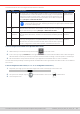
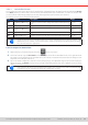
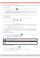

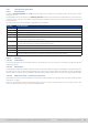
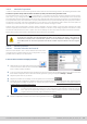
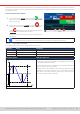
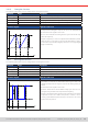
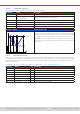
Table Of Contents
- 1. General
- 1.1 About this document
- 1.2 Warranty
- 1.3 Limitation of liability
- 1.4 Disposal of equipment
- 1.5 Product key
- 1.6 Intended usage
- 1.7 Safety
- 1.8 Technical Data
- 1.9 Construction and function
- 1.9.1 General description
- 1.9.2 Block diagram
- 1.9.3 Scope of delivery
- 1.9.4 Accessories
- 1.9.5 Options
- 1.9.6 The control panel (HMI)
- 1.9.7 USB port (rear side)
- 1.9.8 Interface module slot
- 1.9.9 Analog interface
- 1.9.10 “Share BUS” connector
- 1.9.11 “Sense” connector (remote sensing)
- 1.9.12 Master-Slave bus
- 1.9.13 Ethernet port
- 2. Installation & commissioning
- 2.1 Transport and storage
- 2.2 Unpacking and visual check
- 2.3 Installation
- 2.3.1 Safety procedures before installation and use
- 2.3.2 Preparation
- 2.3.3 Installing the device
- 2.3.4 Connection to AC supply
- 2.3.5 Connection to DC sources
- 2.3.6 Connection of remote sensing
- 2.3.7 Grounding of the DC terminal
- 2.3.8 Installation of an interface module
- 2.3.9 Connection of the analog interface
- 2.3.10 Connection of the Share bus
- 2.3.11 Connection of the USB port (rear side)
- 2.3.12 Initial commission
- 2.3.13 Commission after a firmware update or a long period of non-use
- 3. Operation and application
- 3.1 Important notes
- 3.2 Operating modes
- 3.3 Alarm conditions
- 3.4 Manual operation
- 3.5 Remote control
- 3.6 Alarms and monitoring
- 3.7 Locking the control panel (HMI)
- 3.8 Locking the adjustment limits and user profiles
- 3.9 Loading and saving user profiles
- 3.10 The function generator
- 3.10.1 Introduction
- 3.10.2 General
- 3.10.3 Method of operation
- 3.10.4 Manual operation
- 3.10.5 Sine wave function
- 3.10.6 Triangular function
- 3.10.7 Rectangular function
- 3.10.8 Trapezoidal function
- 3.10.9 DIN 40839 function
- 3.10.10 Arbitrary function
- 3.10.11 Ramp function
- 3.10.12 IU table function (XY table)
- 3.10.13 Battery test function
- 3.10.14 MPP tracking function
- 3.10.15 Remote control of the function generator
- 3.11 Other applications
- 4. Service and maintenance
- 5. Contact and support

© EA Elektro-Automatik in 2022, this information is subject to change without notice 6533200840_manual_elr_10000_2u_3kw_en_02
3.10 The function generator
3.10.1 Introduction
The built-in function generator (short: FG) is able to create various signal forms and apply these to the set value of either
voltage or current.
The standard functions are based on an arbitrary generator and directly accessible and congurable using manual control.
In remote control, the fully customizable arbitrary generator replicates these functions with sequence points containing 8
parameters each.
The following functions are retrievable, congurable and controllable:
Function Short description
Sine Sine wave generation with adjustable amplitude, offset and frequency
Triangle Triangular wave signal generation with adjustable amplitude, offset, rise and fall times
Rectangular Rectangular wave signal generation with adjustable amplitude, offset and duty cycle
Trapezoid Trapezoidal wave signal generation with adjustable amplitude, offset, rise time, pulse time, fall time, idle time
DIN 40839 Simulated automobile engine start curve according to DIN 40839 / EN ISO 7637, split into 5 curve sequences,
each with a start voltage, nal voltage and time
Arbitrary Generation of a process with up to 99 freely congurable curve points, each with a start and end value (AC/
DC), start and end frequency, phase angle and total duration
Ramp Generation of a linear rise or fall ramp with start and end values and time before and after the ramp
XY table XY generator, USB stick loadable current curve (table, CSV)
Battery test Battery charge and discharge test with constant or pulsed current, along with Ah, Wh and time counters
MPP tracking Simulation of the characteristic tracking behavior of solar inverters when seeking to nd the maximum
power point (MPP) when being connected to typical sources such as solar panels
3.10.2 General
3.10. 2 .1 Limitations
The function generator is not accessible, neither for manual access nor for remote control, if resistance mode (R mode, also
called UIR) is active.
3.10.2.2 Resolution
Amplitudes generated by the arbitrary generator have an effective resolution of approx. 52428 steps. If the amplitude is very
low and the time long, the device would generate less steps and set multiple identical values after another, generating a
staircase effect. It’s furthermore not possible to generate every possible combination of time and a varying amplitude (slope).
3.10.2.3 Minimum slope / maximum ramp time
Removed since release of KE 3.02 and DR 1.0.2.20 (newer production dates from 03/2022) and 1.0.9 (older production dates
until approx. 01/2022.
Ramps or mixed AC/DC functions where the DC offset varies from start to end don’t have a minimum slope anymore. The
time of a sequence point can now use the full 36000 seconds.