
Manual
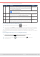
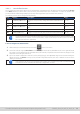
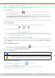

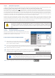
Table Of Contents
- 1. General
- 1.1 About this document
- 1.2 Warranty
- 1.3 Limitation of liability
- 1.4 Disposal of equipment
- 1.5 Product key
- 1.6 Intended usage
- 1.7 Safety
- 1.8 Technical Data
- 1.9 Construction and function
- 1.9.1 General description
- 1.9.2 Block diagram
- 1.9.3 Scope of delivery
- 1.9.4 Accessories
- 1.9.5 Options
- 1.9.6 The control panel (HMI)
- 1.9.7 USB port (rear side)
- 1.9.8 Interface module slot
- 1.9.9 Analog interface
- 1.9.10 “Share BUS” connector
- 1.9.11 “Sense” connector (remote sensing)
- 1.9.12 Master-Slave bus
- 1.9.13 Ethernet port
- 2. Installation & commissioning
- 2.1 Transport and storage
- 2.2 Unpacking and visual check
- 2.3 Installation
- 2.3.1 Safety procedures before installation and use
- 2.3.2 Preparation
- 2.3.3 Installing the device
- 2.3.4 Connection to AC supply
- 2.3.5 Connection to DC sources
- 2.3.6 Connection of remote sensing
- 2.3.7 Grounding of the DC terminal
- 2.3.8 Installation of an interface module
- 2.3.9 Connection of the analog interface
- 2.3.10 Connection of the Share bus
- 2.3.11 Connection of the USB port (rear side)
- 2.3.12 Initial commission
- 2.3.13 Commission after a firmware update or a long period of non-use
- 3. Operation and application
- 3.1 Important notes
- 3.2 Operating modes
- 3.3 Alarm conditions
- 3.4 Manual operation
- 3.5 Remote control
- 3.6 Alarms and monitoring
- 3.7 Locking the control panel (HMI)
- 3.8 Locking the adjustment limits and user profiles
- 3.9 Loading and saving user profiles
- 3.10 The function generator
- 3.10.1 Introduction
- 3.10.2 General
- 3.10.3 Method of operation
- 3.10.4 Manual operation
- 3.10.5 Sine wave function
- 3.10.6 Triangular function
- 3.10.7 Rectangular function
- 3.10.8 Trapezoidal function
- 3.10.9 DIN 40839 function
- 3.10.10 Arbitrary function
- 3.10.11 Ramp function
- 3.10.12 IU table function (XY table)
- 3.10.13 Battery test function
- 3.10.14 MPP tracking function
- 3.10.15 Remote control of the function generator
- 3.11 Other applications
- 4. Service and maintenance
- 5. Contact and support

© EA Elektro-Automatik in 2022, this information is subject to change without notice 6433200840_manual_elr_10000_2u_3kw_en_02
3.9 Loading and saving user proles
The menu Proles serves to select between a default prole and up to 5 user proles. A prole is a collection of all settings
and set values. Upon delivery or after a factory reset all 6 proles have the same settings and all set values are 0. Values
adjusted on the main screen or anywhere else belong to a working prole which can be saved to one of the 5 user proles.
These user proles or the default prole can then be switched. The default prole is read-only.
The purpose of a prole is to load a set of set values, settings limits and monitoring thresholds quickly without having to
readjust these. As all HMI settings are saved in the prole, including language, a prole change can also be accompanied by
a change in HMI language.
On calling up the menu page and selecting a prole the most important settings can be seen, but not changed.
► How to save the current values and settings as a user prole:
1. While the DC input is switched off, tap touch area on
the main screen.
2. In the main menu tap on Proles.
3. In the next screen (see example to the right) choose between
user proles 1-5, which will show the prole’s stored settings
for your verication.
4. Tap on Save/Load and save the settings into the user prole
in the popping up requester “Save prole?” with Save.
All user proles also allow to just edit some settings or values stored in the prole. When doing so, the
changes either need to the be saved to the prole with Save changes or discarded with Cancel before the
prole can be loaded.
Loading a user prole works the same way, but in the requester you would then tap Load under Load prole?.
Alternatively, you may import the prole or export it as le to a USB stick with USB Import/Export.