
Manual
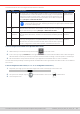
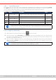
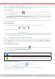

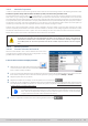
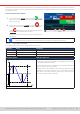
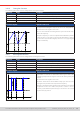
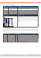
Table Of Contents
- 1. General
- 1.1 About this document
- 1.2 Warranty
- 1.3 Limitation of liability
- 1.4 Disposal of equipment
- 1.5 Product key
- 1.6 Intended usage
- 1.7 Safety
- 1.8 Technical Data
- 1.9 Construction and function
- 1.9.1 General description
- 1.9.2 Block diagram
- 1.9.3 Scope of delivery
- 1.9.4 Accessories
- 1.9.5 Options
- 1.9.6 The control panel (HMI)
- 1.9.7 USB port (rear side)
- 1.9.8 Interface module slot
- 1.9.9 Analog interface
- 1.9.10 “Share BUS” connector
- 1.9.11 “Sense” connector (remote sensing)
- 1.9.12 Master-Slave bus
- 1.9.13 Ethernet port
- 2. Installation & commissioning
- 2.1 Transport and storage
- 2.2 Unpacking and visual check
- 2.3 Installation
- 2.3.1 Safety procedures before installation and use
- 2.3.2 Preparation
- 2.3.3 Installing the device
- 2.3.4 Connection to AC supply
- 2.3.5 Connection to DC sources
- 2.3.6 Connection of remote sensing
- 2.3.7 Grounding of the DC terminal
- 2.3.8 Installation of an interface module
- 2.3.9 Connection of the analog interface
- 2.3.10 Connection of the Share bus
- 2.3.11 Connection of the USB port (rear side)
- 2.3.12 Initial commission
- 2.3.13 Commission after a firmware update or a long period of non-use
- 3. Operation and application
- 3.1 Important notes
- 3.2 Operating modes
- 3.3 Alarm conditions
- 3.4 Manual operation
- 3.5 Remote control
- 3.6 Alarms and monitoring
- 3.7 Locking the control panel (HMI)
- 3.8 Locking the adjustment limits and user profiles
- 3.9 Loading and saving user profiles
- 3.10 The function generator
- 3.10.1 Introduction
- 3.10.2 General
- 3.10.3 Method of operation
- 3.10.4 Manual operation
- 3.10.5 Sine wave function
- 3.10.6 Triangular function
- 3.10.7 Rectangular function
- 3.10.8 Trapezoidal function
- 3.10.9 DIN 40839 function
- 3.10.10 Arbitrary function
- 3.10.11 Ramp function
- 3.10.12 IU table function (XY table)
- 3.10.13 Battery test function
- 3.10.14 MPP tracking function
- 3.10.15 Remote control of the function generator
- 3.11 Other applications
- 4. Service and maintenance
- 5. Contact and support

© EA Elektro-Automatik in 2022, this information is subject to change without notice 6333200840_manual_elr_10000_2u_3kw_en_02
3.7 Locking the control panel (HMI)
In order to avoid the accidental alteration of a value during manual operation the rotary knobs or the touchscreen can be
locked so that no alteration of values will be accepted without prior unlocking.
► How to lock the HMI
1. In the main page, tap the padlock symbol in upper right corner. If the DC input is switched on in this moment, the
lock is immediately effective.
2. Otherwise the Lock screen will appear where you can select to lock the HMI completely or with the exception of the
button On/Off by enabling On/Off possible during HMI lock. Additionally, you can decide to activate the additional
PIN for user interface lock. The device would later request to enter this PIN every time you want to unlock the HMI.
3. Activate the lock with Start. The device will jump back to the main screen and dim it.
If an attempt is made to tap the screen or rotate a knob whilst the HMI is locked, a requester appears in the display asking if
the lock should be disabled.
► How to unlock the HMI
1. Tap any area on the touchscreen or rotate any knob or press the button “On/Off” (only in full lock).
2. This request pop-up will appear: .
3. Unlock the HMI by tapping on Unlock within 5 seconds, otherwise the pop-up will disappear and the HMI remains locked.
In case the additional PIN code lock has been activated in the Lock screen, another requester will pop up, asking you
to enter the PIN before it nally unlocks the HMI.
3.8 Locking the adjustment limits and user proles
In order to avoid the alteration of the adjustment limits (also see
“3.4.4. Adjustment limits”
) by an unprivileged user, the screen
with the adjustment limit settings (“Limits”) can be locked by a PIN code. This will lock group Limits in the Settings menu
and menu Proles until the lock is removed by entering the correct PIN or, in case it has been forgotten, by resetting the
device to factory default.
► How to lock the Limits and Proles
1. While the DC input is switched off, tap the padlock symbol on the main screen. In case the HMI is locked, it has
to be unlocked rst. After this, menu page Lock will be entered.
2. In the switch next to Lock limits and proles with user PIN.
3. Leave the Settings menu.
The same PIN as for the HMI lock is used here. It should be set before activating the Limits lock. See “3.7.
Locking the control panel (HMI)”
Be careful to enable the lock if you are unsure what PIN is currently set. In doubt use ESC to exit the
menu page. In menu page Lock you can dene a different PIN, but not without entering the old one.
► How to unlock the Limits and Proles
1. While the DC input is switched off, tap touch area on the main screen.
2. In the menu tap on HMI setup, then on group Lock.
3. In the group tap on “Unlock limits and proles”. You will be requested to enter the 4-digit PIN.
4. Deactivate the lock by entering the correct PIN.