
Manual
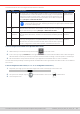
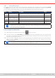
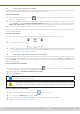

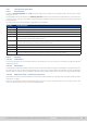
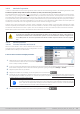
Table Of Contents
- 1. General
- 1.1 About this document
- 1.2 Warranty
- 1.3 Limitation of liability
- 1.4 Disposal of equipment
- 1.5 Product key
- 1.6 Intended usage
- 1.7 Safety
- 1.8 Technical Data
- 1.9 Construction and function
- 1.9.1 General description
- 1.9.2 Block diagram
- 1.9.3 Scope of delivery
- 1.9.4 Accessories
- 1.9.5 Options
- 1.9.6 The control panel (HMI)
- 1.9.7 USB port (rear side)
- 1.9.8 Interface module slot
- 1.9.9 Analog interface
- 1.9.10 “Share BUS” connector
- 1.9.11 “Sense” connector (remote sensing)
- 1.9.12 Master-Slave bus
- 1.9.13 Ethernet port
- 2. Installation & commissioning
- 2.1 Transport and storage
- 2.2 Unpacking and visual check
- 2.3 Installation
- 2.3.1 Safety procedures before installation and use
- 2.3.2 Preparation
- 2.3.3 Installing the device
- 2.3.4 Connection to AC supply
- 2.3.5 Connection to DC sources
- 2.3.6 Connection of remote sensing
- 2.3.7 Grounding of the DC terminal
- 2.3.8 Installation of an interface module
- 2.3.9 Connection of the analog interface
- 2.3.10 Connection of the Share bus
- 2.3.11 Connection of the USB port (rear side)
- 2.3.12 Initial commission
- 2.3.13 Commission after a firmware update or a long period of non-use
- 3. Operation and application
- 3.1 Important notes
- 3.2 Operating modes
- 3.3 Alarm conditions
- 3.4 Manual operation
- 3.5 Remote control
- 3.6 Alarms and monitoring
- 3.7 Locking the control panel (HMI)
- 3.8 Locking the adjustment limits and user profiles
- 3.9 Loading and saving user profiles
- 3.10 The function generator
- 3.10.1 Introduction
- 3.10.2 General
- 3.10.3 Method of operation
- 3.10.4 Manual operation
- 3.10.5 Sine wave function
- 3.10.6 Triangular function
- 3.10.7 Rectangular function
- 3.10.8 Trapezoidal function
- 3.10.9 DIN 40839 function
- 3.10.10 Arbitrary function
- 3.10.11 Ramp function
- 3.10.12 IU table function (XY table)
- 3.10.13 Battery test function
- 3.10.14 MPP tracking function
- 3.10.15 Remote control of the function generator
- 3.11 Other applications
- 4. Service and maintenance
- 5. Contact and support

© EA Elektro-Automatik in 2022, this information is subject to change without notice 6133200840_manual_elr_10000_2u_3kw_en_02
These device alarms can’t be congured and are based on hardware:
Short Long Description
Indication
PF Power Fail AC supply over- or undervoltage. Triggers an alarm in case the AC supply is
out of specication or when the device is cut from supply, for example when
switching it off with the power switch. The DC input will be switched off. The
condition of the DC input after a temporary PF alarm can be determined by the
setting DC input -> State after PF alarm.
Display, analog &
digital interfaces
Acknowledging a PF alarm during runtime can only occur approx. 15 seconds after the
cause of the alarm has gone. Switching the DC input on again requires another approx.
5 seconds of waiting time.
OT OverTempera-
ture
Triggers an alarm in case the internal temperature reaches a certain limit. The
DC input will be switched off. The condition of the DC input after cooling down
can be determined by the setting DC input -> State after OT alarm.
Display, analog &
digital interfaces
MSP Master-Slave
Protection
Triggers an alarm in case the master unit loses contact to any slave unit. The
DC input will be switched off. The alarm can be cleared by reinitializing the MS
system.
Display, digital
interfaces
SF Share Bus
Fail
Can occur in situations where the Share bus signal is damped too much due
to wrong or damaged (short-circuit) BNC cables or simply when at least one of
the Share bus connectors is wired to another device while the alarm reporting
one isn’t congured for master-slave operation. For details also see
3.3.6
.
Display, digital
interfaces
► How to congure the thresholds of the adjustable device alarms
1. While the DC input is switched off tap the touch area on the main screen.
2. In the menu tap on group Protection. On the right-hand side of the screen it will list all device alarms with their adjust-
able thresholds. These are permanently compared to the actual values of voltage, current and power on the DC input.
3. Set the threshold for the protections relevant to your application if the default value of 110% is unsuitable.
The user also has the possibility of selecting whether an additional acoustic signal will be sounded if an alarm or user dened
event occurs.
► How to congure the alarm sound (also see “
“3.4.3. Conguration via the menu”)
1. Swipe with your nger up from the bottom edge of the screen or directly tap on the bottom bar:
2. The quick menu will open. Tap on to activate the alarm sound, or on to deactivate it.
3. Leave the quick menu.