
Manual
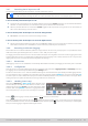
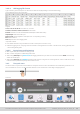
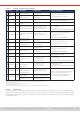
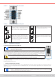
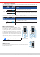
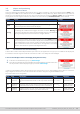
Table Of Contents
- 1. General
- 1.1 About this document
- 1.2 Warranty
- 1.3 Limitation of liability
- 1.4 Disposal of equipment
- 1.5 Product key
- 1.6 Intended usage
- 1.7 Safety
- 1.8 Technical Data
- 1.9 Construction and function
- 1.9.1 General description
- 1.9.2 Block diagram
- 1.9.3 Scope of delivery
- 1.9.4 Accessories
- 1.9.5 Options
- 1.9.6 The control panel (HMI)
- 1.9.7 USB port (rear side)
- 1.9.8 Interface module slot
- 1.9.9 Analog interface
- 1.9.10 “Share BUS” connector
- 1.9.11 “Sense” connector (remote sensing)
- 1.9.12 Master-Slave bus
- 1.9.13 Ethernet port
- 2. Installation & commissioning
- 2.1 Transport and storage
- 2.2 Unpacking and visual check
- 2.3 Installation
- 2.3.1 Safety procedures before installation and use
- 2.3.2 Preparation
- 2.3.3 Installing the device
- 2.3.4 Connection to AC supply
- 2.3.5 Connection to DC sources
- 2.3.6 Connection of remote sensing
- 2.3.7 Grounding of the DC terminal
- 2.3.8 Installation of an interface module
- 2.3.9 Connection of the analog interface
- 2.3.10 Connection of the Share bus
- 2.3.11 Connection of the USB port (rear side)
- 2.3.12 Initial commission
- 2.3.13 Commission after a firmware update or a long period of non-use
- 3. Operation and application
- 3.1 Important notes
- 3.2 Operating modes
- 3.3 Alarm conditions
- 3.4 Manual operation
- 3.5 Remote control
- 3.6 Alarms and monitoring
- 3.7 Locking the control panel (HMI)
- 3.8 Locking the adjustment limits and user profiles
- 3.9 Loading and saving user profiles
- 3.10 The function generator
- 3.10.1 Introduction
- 3.10.2 General
- 3.10.3 Method of operation
- 3.10.4 Manual operation
- 3.10.5 Sine wave function
- 3.10.6 Triangular function
- 3.10.7 Rectangular function
- 3.10.8 Trapezoidal function
- 3.10.9 DIN 40839 function
- 3.10.10 Arbitrary function
- 3.10.11 Ramp function
- 3.10.12 IU table function (XY table)
- 3.10.13 Battery test function
- 3.10.14 MPP tracking function
- 3.10.15 Remote control of the function generator
- 3.11 Other applications
- 4. Service and maintenance
- 5. Contact and support

© EA Elektro-Automatik in 2022, this information is subject to change without notice 6033200840_manual_elr_10000_2u_3kw_en_02
3.6 Alarms and monitoring
3.6.1 Denition of terms
There is a clear distinction between device alarms (see
“3.3. Alarm conditions”
), such as overvoltage protection OVP or over-
heating protection OT, and user dened events such as OVD (overvoltage detection). Whilst device alarms only switch off
the DC input, user dened events can do more. They can also switch off the DC input(Action = Alarm), but can alternatively
simply give an acoustic signal to make the user aware. The actions driven by user dened events can be selected:
Action Impact Example
None User dened event is disabled.
Signal
On reaching the condition which triggers the event, the action Signal will show
a text message in the status area of the display.
Warning
On reaching the condition which triggers the event, the action Warning will
show a text message in the status area of the display and pop up an additional
warning message which can be noticed from a bigger distance.
Alarm
On reaching the condition which triggers the event, the action Alarm will show
a text message in the status area of the display with an additional alarm pop-
up, and additionally emit an acoustic signal (if activated). Furthermore the DC
input is switched off. Most of the device alarms are signaled on the analog
interface, while all can be queried via the digital interfaces.
3.6.2 Device alarm and event handling
A device alarm incident will usually lead to DC input switch-off, the appearance of a pop-up in the middle of the display and,
if activated, an acoustic signal to make the user aware. An alarm must always be acknowledged.
► How to acknowledge an alarm in the display (during manual control)
1. If the alarm is indicated as a pop-up, tap Acknowledge.
2. If the alarm has already been acknowledged, but is still displayed in the status area, then
rst tap the status area to display the pop-up and then Acknowledge.
In order to acknowledge an alarm during analog remote control refer to
“3.5.4.2. Acknowledging device alarms”
. To acknowl-
edge in digital remote control, refer to the external documentation “Programming Guide ModBus & SCPI”.
Some device alarms are congurable:
Short Long Description Range
Indication
OVP OverVoltage
Protection
Triggers an alarm as soon as the voltage on the DC input
reaches the dened threshold. The DC input will be switched
off.
0 V...1.1*U
Nom
Display, analog &
digital interfaces
OCP OverCurrent
Protection
Triggers an alarm as soon as the current in the DC input reach-
es the dened threshold. The DC input will be switched off.
0 A ...1.1*I
Nom
Display, analog &
digital interfaces
OPP OverPower
Protection
Triggers an alarm as soon as the input power reaches the
dened threshold. The DC input will be switched off.
0 W...1.1*P
Nom
Display, analog &
digital interfaces