
Manual
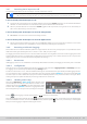
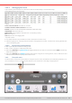
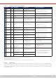
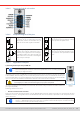
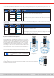
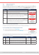
Table Of Contents
- 1. General
- 1.1 About this document
- 1.2 Warranty
- 1.3 Limitation of liability
- 1.4 Disposal of equipment
- 1.5 Product key
- 1.6 Intended usage
- 1.7 Safety
- 1.8 Technical Data
- 1.9 Construction and function
- 1.9.1 General description
- 1.9.2 Block diagram
- 1.9.3 Scope of delivery
- 1.9.4 Accessories
- 1.9.5 Options
- 1.9.6 The control panel (HMI)
- 1.9.7 USB port (rear side)
- 1.9.8 Interface module slot
- 1.9.9 Analog interface
- 1.9.10 “Share BUS” connector
- 1.9.11 “Sense” connector (remote sensing)
- 1.9.12 Master-Slave bus
- 1.9.13 Ethernet port
- 2. Installation & commissioning
- 2.1 Transport and storage
- 2.2 Unpacking and visual check
- 2.3 Installation
- 2.3.1 Safety procedures before installation and use
- 2.3.2 Preparation
- 2.3.3 Installing the device
- 2.3.4 Connection to AC supply
- 2.3.5 Connection to DC sources
- 2.3.6 Connection of remote sensing
- 2.3.7 Grounding of the DC terminal
- 2.3.8 Installation of an interface module
- 2.3.9 Connection of the analog interface
- 2.3.10 Connection of the Share bus
- 2.3.11 Connection of the USB port (rear side)
- 2.3.12 Initial commission
- 2.3.13 Commission after a firmware update or a long period of non-use
- 3. Operation and application
- 3.1 Important notes
- 3.2 Operating modes
- 3.3 Alarm conditions
- 3.4 Manual operation
- 3.5 Remote control
- 3.6 Alarms and monitoring
- 3.7 Locking the control panel (HMI)
- 3.8 Locking the adjustment limits and user profiles
- 3.9 Loading and saving user profiles
- 3.10 The function generator
- 3.10.1 Introduction
- 3.10.2 General
- 3.10.3 Method of operation
- 3.10.4 Manual operation
- 3.10.5 Sine wave function
- 3.10.6 Triangular function
- 3.10.7 Rectangular function
- 3.10.8 Trapezoidal function
- 3.10.9 DIN 40839 function
- 3.10.10 Arbitrary function
- 3.10.11 Ramp function
- 3.10.12 IU table function (XY table)
- 3.10.13 Battery test function
- 3.10.14 MPP tracking function
- 3.10.15 Remote control of the function generator
- 3.11 Other applications
- 4. Service and maintenance
- 5. Contact and support

© EA Elektro-Automatik in 2022, this information is subject to change without notice 5933200840_manual_elr_10000_2u_3kw_en_02
• Remote control has not been activated
In this mode of operation pin REM-SB can serve as lock, preventing the DC input from being switched on by any means. This
results in following possible situations:
DC
terminal
+
Level on
pin REM-
SB
+
Parameter
„REM-SB
Level“
Behavior
is off
+
HIGH
+
Normal
The DC input isn’t locked. It can be switched on by pushbutton “On/Off”
(front panel) or via command from digital interface.
LOW
+
Inverted
+
HIGH
+
Inverted
The DC input is locked. It can’t be switched on by pushbutton “On/Off”
(front panel) or via command from digital interface. When trying to switch
on, a pop-up in the display resp. an error message will be generated.
LOW
+
Normal
In case the DC input is already switched on, toggling the pin will switch the DC input off, similar to what it does in analog
remote control:
DC
terminal
+
Level on
pin REM-
SB
+
Parameter
„REM-SB
Level“
Behavior
is on
+
HIGH
+
Normal
The DC input remains on, nothing is locked. It can be switched on or off
by pushbutton or digital command.
LOW
+
Inverted
+
HIGH
+
Inverted
The DC input will be switched off and locked. Later it can be switched on
again by toggling the pin. During lock, pushbutton or digital command
can delete the request to switch on by pin.
LOW
+
Normal
b) Remote control of current and power
Requires remote control to be activated (pin REMOTE = LOW)
The set values PSEL and CSEL are generated from, for example,
the reference voltage VREF, using potentiometers for each. Hence
the power supply can selectively work in current limiting or power
limiting mode. According to the specication of max. 5 mA load for
the VREF output, potentiometers of at least 10 kΩ must be used.
The voltage set value VSEL is directly connected to VREF and will
thus be permanently 100%. This also means that the device can
only work in source mode.
If the control voltage is fed in from an external source it’s neces-
sary to consider the input voltage ranges for set values (0...5V oder
0...10 V).
When using the voltage range 0...5 V the effec-
tive resolution of set values and actual values
halves.
Example with external
voltage source
Example with
potentiometers
c) Reading actual values
The AI provides the DC input values as current and voltage monitor. These can be read using
a standard multimeter or similar.