
Manual
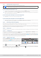
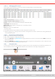
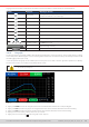
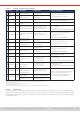
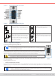
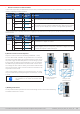
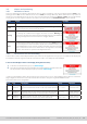
Table Of Contents
- 1. General
- 1.1 About this document
- 1.2 Warranty
- 1.3 Limitation of liability
- 1.4 Disposal of equipment
- 1.5 Product key
- 1.6 Intended usage
- 1.7 Safety
- 1.8 Technical Data
- 1.9 Construction and function
- 1.9.1 General description
- 1.9.2 Block diagram
- 1.9.3 Scope of delivery
- 1.9.4 Accessories
- 1.9.5 Options
- 1.9.6 The control panel (HMI)
- 1.9.7 USB port (rear side)
- 1.9.8 Interface module slot
- 1.9.9 Analog interface
- 1.9.10 “Share BUS” connector
- 1.9.11 “Sense” connector (remote sensing)
- 1.9.12 Master-Slave bus
- 1.9.13 Ethernet port
- 2. Installation & commissioning
- 2.1 Transport and storage
- 2.2 Unpacking and visual check
- 2.3 Installation
- 2.3.1 Safety procedures before installation and use
- 2.3.2 Preparation
- 2.3.3 Installing the device
- 2.3.4 Connection to AC supply
- 2.3.5 Connection to DC sources
- 2.3.6 Connection of remote sensing
- 2.3.7 Grounding of the DC terminal
- 2.3.8 Installation of an interface module
- 2.3.9 Connection of the analog interface
- 2.3.10 Connection of the Share bus
- 2.3.11 Connection of the USB port (rear side)
- 2.3.12 Initial commission
- 2.3.13 Commission after a firmware update or a long period of non-use
- 3. Operation and application
- 3.1 Important notes
- 3.2 Operating modes
- 3.3 Alarm conditions
- 3.4 Manual operation
- 3.5 Remote control
- 3.6 Alarms and monitoring
- 3.7 Locking the control panel (HMI)
- 3.8 Locking the adjustment limits and user profiles
- 3.9 Loading and saving user profiles
- 3.10 The function generator
- 3.10.1 Introduction
- 3.10.2 General
- 3.10.3 Method of operation
- 3.10.4 Manual operation
- 3.10.5 Sine wave function
- 3.10.6 Triangular function
- 3.10.7 Rectangular function
- 3.10.8 Trapezoidal function
- 3.10.9 DIN 40839 function
- 3.10.10 Arbitrary function
- 3.10.11 Ramp function
- 3.10.12 IU table function (XY table)
- 3.10.13 Battery test function
- 3.10.14 MPP tracking function
- 3.10.15 Remote control of the function generator
- 3.11 Other applications
- 4. Service and maintenance
- 5. Contact and support

© EA Elektro-Automatik in 2022, this information is subject to change without notice 5833200840_manual_elr_10000_2u_3kw_en_02
3.5.4.5 Overview of the D-sub socket
3.5.4.6 Simplied diagram of the pins
++
Digital Input (DI)
It requires to use a switch with low resis-
tance (relay, switch, circuit breaker etc.) in
order to send a clean signal to the DGND.
V~0.5
AGND
Analog Input (AI)
High resistance input (impedance >40 kΩ)
for an operation amplier circuit.
4K7
12 V
+10V
Digital Output (DO)
A quasi open collector, realized as high re-
sistance pull-up against the internal supply.
In condition LOW it can’t drive any load, only
sink small current, as shown in the diagram
with a relay as example.
V~2
AGND
Analog Output (AO)
Output from an operation amplier circuit,
low impedance. See specications table
above.
3.5.4.7 Application examples
a) Switching the DC input with pin REM-SB
A digital output, e.g. from a PLC, may be unable to cleanly pull down the pin as it may not
be of suciently low resistance. Check the specication of the controlling application.
Also see pin diagrams above.
In analog remote control, pin REM-SB is be used to switch the DC input of the device on and off. This function
is also available without analog remote control being active and can on the one hand block the DC input
from being switched on in manual or digital remote control and on the other hand the pin can switch the DC
input on or off, but not standalone. See below at “Remote control has not been activated”.
REM-SB cannot serve as a safety stop switch to securely deactivate the DC input in case
of emergency! For that an external emergency stop system is required.
It’s recommended that a low resistance contact such as a switch, relay or transistor is used to switch the
pin to ground (DGND).
Following situations can occur:
• Remote control has been activated
During remote control via analog interface, only pin REM-SB determines the states of the DC input, according to the level
denitions in
3.5.4.3
. The logical function and the default levels can be inverted by a parameter in the setup menu of the
device. See
3.4.3.1
.
If the pin is unconnected or the connected contact is open, the pin will be HIGH. With setting “Analog in-
terface” -> “REM-SB level” being set to “Normal”, it requests to switch the DC input on. So when activating
remote control, the DC input will instantly switch on.