
Manual
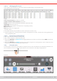
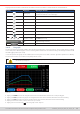
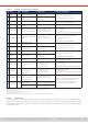
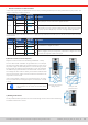
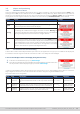
Table Of Contents
- 1. General
- 1.1 About this document
- 1.2 Warranty
- 1.3 Limitation of liability
- 1.4 Disposal of equipment
- 1.5 Product key
- 1.6 Intended usage
- 1.7 Safety
- 1.8 Technical Data
- 1.9 Construction and function
- 1.9.1 General description
- 1.9.2 Block diagram
- 1.9.3 Scope of delivery
- 1.9.4 Accessories
- 1.9.5 Options
- 1.9.6 The control panel (HMI)
- 1.9.7 USB port (rear side)
- 1.9.8 Interface module slot
- 1.9.9 Analog interface
- 1.9.10 “Share BUS” connector
- 1.9.11 “Sense” connector (remote sensing)
- 1.9.12 Master-Slave bus
- 1.9.13 Ethernet port
- 2. Installation & commissioning
- 2.1 Transport and storage
- 2.2 Unpacking and visual check
- 2.3 Installation
- 2.3.1 Safety procedures before installation and use
- 2.3.2 Preparation
- 2.3.3 Installing the device
- 2.3.4 Connection to AC supply
- 2.3.5 Connection to DC sources
- 2.3.6 Connection of remote sensing
- 2.3.7 Grounding of the DC terminal
- 2.3.8 Installation of an interface module
- 2.3.9 Connection of the analog interface
- 2.3.10 Connection of the Share bus
- 2.3.11 Connection of the USB port (rear side)
- 2.3.12 Initial commission
- 2.3.13 Commission after a firmware update or a long period of non-use
- 3. Operation and application
- 3.1 Important notes
- 3.2 Operating modes
- 3.3 Alarm conditions
- 3.4 Manual operation
- 3.5 Remote control
- 3.6 Alarms and monitoring
- 3.7 Locking the control panel (HMI)
- 3.8 Locking the adjustment limits and user profiles
- 3.9 Loading and saving user profiles
- 3.10 The function generator
- 3.10.1 Introduction
- 3.10.2 General
- 3.10.3 Method of operation
- 3.10.4 Manual operation
- 3.10.5 Sine wave function
- 3.10.6 Triangular function
- 3.10.7 Rectangular function
- 3.10.8 Trapezoidal function
- 3.10.9 DIN 40839 function
- 3.10.10 Arbitrary function
- 3.10.11 Ramp function
- 3.10.12 IU table function (XY table)
- 3.10.13 Battery test function
- 3.10.14 MPP tracking function
- 3.10.15 Remote control of the function generator
- 3.11 Other applications
- 4. Service and maintenance
- 5. Contact and support

© EA Elektro-Automatik in 2022, this information is subject to change without notice 5733200840_manual_elr_10000_2u_3kw_en_02
3.5.4.3 Analog interface specication
Pin Name
Type
(1
Description Default levels Electrical specications
1 VSEL AI Voltage set value
0…10 V or 0...5 V correspond
to 0..100% of U
Nom
Accuracy 0-5 V range: < 0.4%
(5
Accuracy 0-10 V range: < 0.2%
(5
Input impedance R
i
>40 k...100 k
2 CSEL AI
Current set value
(source & sink)
0…10 V or 0...5 V correspond
to 0..100% of I
Nom
3 VREF AO Reference voltage 10 V or 5 V
Tolerance < 0.2% at I
max
= +5 mA
Short-circuit-proof against AGND
4 DGND POT
Ground for all digital
signals
For control and status signals
5 REMOTE DI
Switches between man-
ual and remote control
Remote = LOW, U
Low
<1 V
Manual = HIGH, U
High
>4 V
Manual, if pin not wired
Voltage range = 0…30 V
I
Max
= -1 mA at 5 V
U
LOW to HIGH typ.
= 3 V
Rec’d sender: Open collector against DGND
6 ALARMS 1 DO
Overheating /power fail
alarm
Alarm = HIGH, U
High
> 4 V
No alarm = LOW, U
Low
<1 V
Quasi open collector with pull-up against Vcc
(2
With 5 V on the pin max. ow +1 mA
I
Max
= -10 mA at U
CE
= 0,3 V
U
Max
= 30 V
Short-circuit-proof against DGND
7 RSEL AI
Resistance value
(source & sink)
0…10 V or 0...5 V correspond
to R
Min
...R
Max
Accuracy 0-5 V range: < 0.4%
(5
Accuracy 0-10 V range: < 0.2%
(5
Input impedance R
i
>40 k...100 k
8 PSEL AI
Power set value
(source & sink)
0…10 V or 0...5 V correspond
to 0..100% of P
Nom
9 VMON AO Actual voltage
0…10 V or 0...5 V correspond
to 0..100% of U
Nom
(5
Accuracy 0-5 V range: < 0.4%
(5
Accuracy 0-10 V range: < 0.2%
(5
I
Max
= +2 mA
Short-circuit-proof against AGND
10 CMON AO Actual current
0…10 V or 0...5 V correspond
to 0..100% of I
Nom
(5
11 AGND POT
Ground for all analog
signals
For xSEL, xMON and VREF
12 R-ACTIVE DI R mode on / off
Off = LOW, U
Low
<1 V
On = HIGH, U
High
>4 V
On, if pin not wired
Voltage range = 0…30 V
I
Max
= -1 mA at 5 V
U
LOW to HIGH typ.
= 3 V
Rec’d sender: Open collector against DGND
13 REM-SB DI
DC input OFF
(DC input ON)
(ACK alarms
(4
)
Off = LOW, U
Low
<1 V
On = HIGH, U
High
>4 V
On, if pin not wired
Voltage range = 0…30 V
I
Max
= +1 mA at 5 V
Rec’d sender: Open collector against DGND
14 ALARMS 2 DO
Overvoltage alarm
Overcurrent alarm
Overpower alarm
Alarm = HIGH, U
High
> 4 V
No alarm = LOW, U
Low
<1 V
Quasi open collector with pull-up against Vcc
(2
With 5 V on the pin max. ow +1 mA
I
Max
= -10 mA at U
CE
= 0,3 V, U
Max
= 30 V
Short-circuit-proof against DGND
15 STATUS
(3
DO
Constant voltage regu-
lation active
CV = LOW, U
Low
<1 V
CC/CP/CR = HIGH, U
High
>4 V
DC input
Off = LOW, U
Low
<1 V
On = HIGH, U
High
>4 V
(1 AI = Analog Input, AO = Analog Output, DI = Digital Input, DO = Digital Output, POT = Potential
(2 Internal Vcc approx. 10 V
(3 Only one of both signals possible, see section
3.4.3.1
(4 Only during remote control
(5 The error of a set value input adds to the general error of the related value on the DC input of the device
3.5.4.4 Resolution
The analog interface is internally sampled and processed by a digital micro-controller. This causes a limited resolution of
analog steps. The effective resolution is the same for set values (VSEL etc.) and actual values (VMON/CMON). It’s 26214
steps when working in the 10 V range. In the 5 V range this resolution halves. Due to tolerances, the truly achievable resolution
can be slightly lower.