
Manual
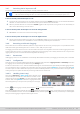
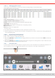
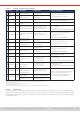
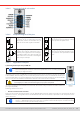
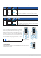
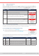
Table Of Contents
- 1. General
- 1.1 About this document
- 1.2 Warranty
- 1.3 Limitation of liability
- 1.4 Disposal of equipment
- 1.5 Product key
- 1.6 Intended usage
- 1.7 Safety
- 1.8 Technical Data
- 1.9 Construction and function
- 1.9.1 General description
- 1.9.2 Block diagram
- 1.9.3 Scope of delivery
- 1.9.4 Accessories
- 1.9.5 Options
- 1.9.6 The control panel (HMI)
- 1.9.7 USB port (rear side)
- 1.9.8 Interface module slot
- 1.9.9 Analog interface
- 1.9.10 “Share BUS” connector
- 1.9.11 “Sense” connector (remote sensing)
- 1.9.12 Master-Slave bus
- 1.9.13 Ethernet port
- 2. Installation & commissioning
- 2.1 Transport and storage
- 2.2 Unpacking and visual check
- 2.3 Installation
- 2.3.1 Safety procedures before installation and use
- 2.3.2 Preparation
- 2.3.3 Installing the device
- 2.3.4 Connection to AC supply
- 2.3.5 Connection to DC sources
- 2.3.6 Connection of remote sensing
- 2.3.7 Grounding of the DC terminal
- 2.3.8 Installation of an interface module
- 2.3.9 Connection of the analog interface
- 2.3.10 Connection of the Share bus
- 2.3.11 Connection of the USB port (rear side)
- 2.3.12 Initial commission
- 2.3.13 Commission after a firmware update or a long period of non-use
- 3. Operation and application
- 3.1 Important notes
- 3.2 Operating modes
- 3.3 Alarm conditions
- 3.4 Manual operation
- 3.5 Remote control
- 3.6 Alarms and monitoring
- 3.7 Locking the control panel (HMI)
- 3.8 Locking the adjustment limits and user profiles
- 3.9 Loading and saving user profiles
- 3.10 The function generator
- 3.10.1 Introduction
- 3.10.2 General
- 3.10.3 Method of operation
- 3.10.4 Manual operation
- 3.10.5 Sine wave function
- 3.10.6 Triangular function
- 3.10.7 Rectangular function
- 3.10.8 Trapezoidal function
- 3.10.9 DIN 40839 function
- 3.10.10 Arbitrary function
- 3.10.11 Ramp function
- 3.10.12 IU table function (XY table)
- 3.10.13 Battery test function
- 3.10.14 MPP tracking function
- 3.10.15 Remote control of the function generator
- 3.11 Other applications
- 4. Service and maintenance
- 5. Contact and support

© EA Elektro-Automatik in 2022, this information is subject to change without notice 5633200840_manual_elr_10000_2u_3kw_en_02
3.5.4 Remote control via the analog interface
3.5.4.1 General
The galvanically isolated, 15-pole analog interface, as built-in and below referenced in short form as AI, is located on the rear
side of the device offers the following possibilities:
• Remote control of current, voltage, power and resistance
• Remote status monitoring (CV, DC input)
• Remote alarm monitoring (OT, OVP, PF, OCP, OPP)
• Remote monitoring of actual values
• Remote on/off switching of the DC input
Setting the three set values of voltage, current and power via the analog interface must always be done concurrently. It
means, for example, that the voltage can’t be given via the AI and current and power set by the rotary knobs or vice versa.
The internal resistance set value can additionally be adjusted.
Analog set values can be supplied by an external voltage or generated from the reference voltage on pin 3. As soon as remote
control via the analog interface is activated, the displayed set values will be those provided by the interface. The AI can be
operated in the common voltage ranges 0...5 V and 0...10 V, both representing 0...100% of the nominal value. The selection of
the voltage range can be done in the device setup. See section
“3.4.3. Conguration via the menu”
for details. The reference
voltage sent out from pin 3 (VREF) will be adapted accordingly:
0-5 V: Reference voltage = 5 V, 0...5 V set value (VSEL, CSEL, PSEL, RSEL) correspond to 0...100% of the rated value or R
Min
...
R
Max
, 0...100% of the actual values correspond to 0...5 V at the outputs CMON and VMON, at least as long these two pins are
still congured for the default (see section
“3.4.3. Conguration via the menu”
).
0-10 V: Reference voltage = 10 V, 0...10 V set value (VSEL, CSEL, PSEL, RSEL) correspond to 0...100% of the rated value or
R
Min
...R
Max
, 0...100% of the actual values correspond to 0...10 V at the outputs CMON and VMON, at least as long these two
pins are still congured for the default (see section
“3.4.3. Conguration via the menu”
).
All set values are always additionally limited to the corresponding adjustment limits (U-max, I-max etc.), which would clip
setting excess values for the DC input. Also see section
“3.4.4. Adjustment limits”
.
Before you begin, please read these important notes about the use of the interface:
After powering the device and during the start phase the AI signals undened statuses on the output pins.
Those must be ignored until it’s ready to work.
• Analog remote control of the device must be activated by switching pin REMOTE (5) rst. Only exception is pin REM-SB,
which can be used independently
• Before the hardware is connected that will control the analog interface, it shall be checked that it can’t provide voltage to
the pins higher than specied
• Set value inputs, such as VSEL, CSEL, PSEL and RSEL (if R mode is activated), must not be left unconnected (i.e. oating)
during analog remote control. In case any of the set values is not used for adjustment, it can be tied to a dened level or
connected to pin VREF, so it gives 100%
3.5.4.2 Acknowledging device alarms
In case of a device alarm occurring during remote control via analog interface, the DC input will be switched off the same way
as in manual control. The device would indicate an alarm (see
3.6.2
) in the front display and, if activated, acoustically and also
signal most of them on the analog interface. Which alarms actually are signaled can be set up in the device conguration
menu (see
“3.4.3.1. Sub menu “Settings””
).
Most device alarms have to be acknowledged (also see
“3.6.2. Device alarm and event handling”).
Acknowledgment is done
with pin REM-SB switching the DC input off and on again, which represents a HIGH-LOW-HIGH signal (min. 50ms for LOW),
when using the default level setting for this pin.