
Manual
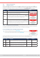
Table Of Contents
- 1. General
- 1.1 About this document
- 1.2 Warranty
- 1.3 Limitation of liability
- 1.4 Disposal of equipment
- 1.5 Product key
- 1.6 Intended usage
- 1.7 Safety
- 1.8 Technical Data
- 1.9 Construction and function
- 1.9.1 General description
- 1.9.2 Block diagram
- 1.9.3 Scope of delivery
- 1.9.4 Accessories
- 1.9.5 Options
- 1.9.6 The control panel (HMI)
- 1.9.7 USB port (rear side)
- 1.9.8 Interface module slot
- 1.9.9 Analog interface
- 1.9.10 “Share BUS” connector
- 1.9.11 “Sense” connector (remote sensing)
- 1.9.12 Master-Slave bus
- 1.9.13 Ethernet port
- 2. Installation & commissioning
- 2.1 Transport and storage
- 2.2 Unpacking and visual check
- 2.3 Installation
- 2.3.1 Safety procedures before installation and use
- 2.3.2 Preparation
- 2.3.3 Installing the device
- 2.3.4 Connection to AC supply
- 2.3.5 Connection to DC sources
- 2.3.6 Connection of remote sensing
- 2.3.7 Grounding of the DC terminal
- 2.3.8 Installation of an interface module
- 2.3.9 Connection of the analog interface
- 2.3.10 Connection of the Share bus
- 2.3.11 Connection of the USB port (rear side)
- 2.3.12 Initial commission
- 2.3.13 Commission after a firmware update or a long period of non-use
- 3. Operation and application
- 3.1 Important notes
- 3.2 Operating modes
- 3.3 Alarm conditions
- 3.4 Manual operation
- 3.5 Remote control
- 3.6 Alarms and monitoring
- 3.7 Locking the control panel (HMI)
- 3.8 Locking the adjustment limits and user profiles
- 3.9 Loading and saving user profiles
- 3.10 The function generator
- 3.10.1 Introduction
- 3.10.2 General
- 3.10.3 Method of operation
- 3.10.4 Manual operation
- 3.10.5 Sine wave function
- 3.10.6 Triangular function
- 3.10.7 Rectangular function
- 3.10.8 Trapezoidal function
- 3.10.9 DIN 40839 function
- 3.10.10 Arbitrary function
- 3.10.11 Ramp function
- 3.10.12 IU table function (XY table)
- 3.10.13 Battery test function
- 3.10.14 MPP tracking function
- 3.10.15 Remote control of the function generator
- 3.11 Other applications
- 4. Service and maintenance
- 5. Contact and support

© EA Elektro-Automatik in 2022, this information is subject to change without notice 5533200840_manual_elr_10000_2u_3kw_en_02
3.5.3.3 Interface monitoring
Interface monitoring is a congurable functionality introduced in rmwares KE 2.06 and HMI 2.08. Its goal is to monitor (or
supervise) the communication line between the device and a superior control unit, such as PC or PLC, and to ensure that the
device wouldn’t continue working uncontrolled in case the communication line fails. A failing line can mean that it’s either
physically interrupted (damaged cable, bad contact, cable pulled) or the interface port inside the device hangs.
The monitoring is always only valid for one of the digital interfaces, the one being used for remote control. It thus means
that the monitoring can become temporarily inactive when the device leaves remote control. It’s furthermore based on a
user-denable timeout which would run out if not at least one message is sent to the device within the given time frame.
After every message, the timeout would start again and reset with the next message coming. In case it runs out, following
reaction of the device is dened:
• Exit remote control
• In case the DC input is switched on, it either switches it off or leaves it on, as dened by the parameter DC input -> State
after remote (see
3.4.3.1
)
Notes for the operation:
• The timeout of the monitoring can be changed anytime via remote control; the new value would only be valid after the
current timeout has elapsed
• The interface monitoring doesn’t deactivate the Ethernet connection timeout (see
3.4.3.6
), so these two timeouts can overlap