
Manual
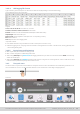
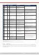
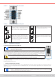
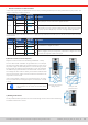
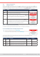
Table Of Contents
- 1. General
- 1.1 About this document
- 1.2 Warranty
- 1.3 Limitation of liability
- 1.4 Disposal of equipment
- 1.5 Product key
- 1.6 Intended usage
- 1.7 Safety
- 1.8 Technical Data
- 1.9 Construction and function
- 1.9.1 General description
- 1.9.2 Block diagram
- 1.9.3 Scope of delivery
- 1.9.4 Accessories
- 1.9.5 Options
- 1.9.6 The control panel (HMI)
- 1.9.7 USB port (rear side)
- 1.9.8 Interface module slot
- 1.9.9 Analog interface
- 1.9.10 “Share BUS” connector
- 1.9.11 “Sense” connector (remote sensing)
- 1.9.12 Master-Slave bus
- 1.9.13 Ethernet port
- 2. Installation & commissioning
- 2.1 Transport and storage
- 2.2 Unpacking and visual check
- 2.3 Installation
- 2.3.1 Safety procedures before installation and use
- 2.3.2 Preparation
- 2.3.3 Installing the device
- 2.3.4 Connection to AC supply
- 2.3.5 Connection to DC sources
- 2.3.6 Connection of remote sensing
- 2.3.7 Grounding of the DC terminal
- 2.3.8 Installation of an interface module
- 2.3.9 Connection of the analog interface
- 2.3.10 Connection of the Share bus
- 2.3.11 Connection of the USB port (rear side)
- 2.3.12 Initial commission
- 2.3.13 Commission after a firmware update or a long period of non-use
- 3. Operation and application
- 3.1 Important notes
- 3.2 Operating modes
- 3.3 Alarm conditions
- 3.4 Manual operation
- 3.5 Remote control
- 3.6 Alarms and monitoring
- 3.7 Locking the control panel (HMI)
- 3.8 Locking the adjustment limits and user profiles
- 3.9 Loading and saving user profiles
- 3.10 The function generator
- 3.10.1 Introduction
- 3.10.2 General
- 3.10.3 Method of operation
- 3.10.4 Manual operation
- 3.10.5 Sine wave function
- 3.10.6 Triangular function
- 3.10.7 Rectangular function
- 3.10.8 Trapezoidal function
- 3.10.9 DIN 40839 function
- 3.10.10 Arbitrary function
- 3.10.11 Ramp function
- 3.10.12 IU table function (XY table)
- 3.10.13 Battery test function
- 3.10.14 MPP tracking function
- 3.10.15 Remote control of the function generator
- 3.11 Other applications
- 4. Service and maintenance
- 5. Contact and support

© EA Elektro-Automatik in 2022, this information is subject to change without notice 5433200840_manual_elr_10000_2u_3kw_en_02
3.5 Remote control
3.5.1 General
Remote control is possible via one of the built-in interfaces (analog, USB, Ethernet) or via one of the optional interface modules.
One of the digital interface is the master-slave bus. It means that a Slave model is supposed to be controlled from a master
unit via the master-slave bus. Controlling a Slave device via its rear USB port is considered an exception.
Important here is that only the analog or any digital interface can be in control. It means that if an attempt was made to switch
to remote control via the digital interface whilst analog remote control is active (pin REMOTE = LOW) the device would report
an error via the digital interface. In the opposite direction, a switch-over via pin REMOTE would be ignored. However, status
monitoring and reading of values are always possible.
3.5.2 Control locations
Control locations are those locations from where the device can be controlled. Essentially there are two: at the device (manual
operation) and external (remote control). The following locations are dened:
Displayed location Description
Remote: None If neither of the other locations is displayed then manual control is active and access from
the analog and digital interfaces is allowed.
Remote: <interface_name> Remote control via any interface is active
Local Remote control is locked, only manual operation is allowed.
Remote control may be allowed or inhibited using the setting Allow remote control (see
“3.4.3.1. Sub menu “Settings””
). In
inhibited condition the status “Local” will be displayed top right. Activating the inhibit can be useful if the device is remotely
controlled by software or some electronic device, but it’s required to make adjustments at the device or deal with emergency.
Activating condition Local causes the following:
• If remote control via the digital interface is active (e. g. Remote: USB), then it’s immediately terminated and in order to con-
tinue remote control once Local is no longer active, it has to be reactivated at the PC
• If remote control via the analog interface is active (Remote: Analog), then it’s temporarily interrupted until remote control is
allowed again by deactivating Local, because pin REMOTE continues to signal “remote control = on”, unless this has been
changed during the Local period.
3.5.3 Remote control via a digital interface
3.5.3.1 Selecting an interface
In addition to the built-in USB and Ethernet ports, all models of this series support the following optionally available interface
modules:
Short ID Type Ports Description*
IF-AB-CANO CANopen 1 CANopen slave with generic EDS
IF-AB-RS232 RS232 1 Standard RS232, serial
IF-AB-PBUS Probus 1 Probus DP-V1 slave
IF-AB-PNET1P ProNet 1 Pronet DP-V1 slave
IF-AB-PNET2P ProNet 2 Pronet DP-V1 slave, with switch
IF-AB-CAN CAN 1 CAN 2.0 A / 2.0 B
IF-AB-ECT EtherCAT 2 Standard EtherCAT slave with CoE
IF-AB-MBUS1P ModBus TCP 1 ModBus TCP protocol via Ethernet
IF-AB-MBUS2P ModBus TCP 2 ModBus TCP protocol via Ethernet
* For technical details of the various modules see the extra documentation “Programming Guide Modbus & SCPI”
3.5.3.2 Programming
Programming details for the rear interfaces, the communication protocols etc. are to be found in the documentation “Pro-
gramming Guide ModBus & SCPI“ which is supplied on the included USB stick or which is available as download from the
manufacturer’s website.