
Manual
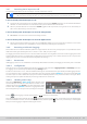
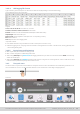
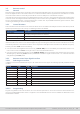
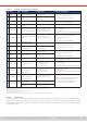
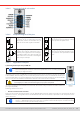
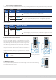
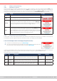
Table Of Contents
- 1. General
- 1.1 About this document
- 1.2 Warranty
- 1.3 Limitation of liability
- 1.4 Disposal of equipment
- 1.5 Product key
- 1.6 Intended usage
- 1.7 Safety
- 1.8 Technical Data
- 1.9 Construction and function
- 1.9.1 General description
- 1.9.2 Block diagram
- 1.9.3 Scope of delivery
- 1.9.4 Accessories
- 1.9.5 Options
- 1.9.6 The control panel (HMI)
- 1.9.7 USB port (rear side)
- 1.9.8 Interface module slot
- 1.9.9 Analog interface
- 1.9.10 “Share BUS” connector
- 1.9.11 “Sense” connector (remote sensing)
- 1.9.12 Master-Slave bus
- 1.9.13 Ethernet port
- 2. Installation & commissioning
- 2.1 Transport and storage
- 2.2 Unpacking and visual check
- 2.3 Installation
- 2.3.1 Safety procedures before installation and use
- 2.3.2 Preparation
- 2.3.3 Installing the device
- 2.3.4 Connection to AC supply
- 2.3.5 Connection to DC sources
- 2.3.6 Connection of remote sensing
- 2.3.7 Grounding of the DC terminal
- 2.3.8 Installation of an interface module
- 2.3.9 Connection of the analog interface
- 2.3.10 Connection of the Share bus
- 2.3.11 Connection of the USB port (rear side)
- 2.3.12 Initial commission
- 2.3.13 Commission after a firmware update or a long period of non-use
- 3. Operation and application
- 3.1 Important notes
- 3.2 Operating modes
- 3.3 Alarm conditions
- 3.4 Manual operation
- 3.5 Remote control
- 3.6 Alarms and monitoring
- 3.7 Locking the control panel (HMI)
- 3.8 Locking the adjustment limits and user profiles
- 3.9 Loading and saving user profiles
- 3.10 The function generator
- 3.10.1 Introduction
- 3.10.2 General
- 3.10.3 Method of operation
- 3.10.4 Manual operation
- 3.10.5 Sine wave function
- 3.10.6 Triangular function
- 3.10.7 Rectangular function
- 3.10.8 Trapezoidal function
- 3.10.9 DIN 40839 function
- 3.10.10 Arbitrary function
- 3.10.11 Ramp function
- 3.10.12 IU table function (XY table)
- 3.10.13 Battery test function
- 3.10.14 MPP tracking function
- 3.10.15 Remote control of the function generator
- 3.11 Other applications
- 4. Service and maintenance
- 5. Contact and support

© EA Elektro-Automatik in 2022, this information is subject to change without notice 5233200840_manual_elr_10000_2u_3kw_en_02
3.4.8.4 USB logging le format
Type: text le in german/european or US american CSV format (depending on the selected setting)
Layout (default german format shown):
Legend:
U set / I set / P set / R set: Set values U, I, P and R
U actual / I actual / P actual / R actual: Actual values
R mode: Resistance mode activated/deactivated (also called ‘UIR mode’)
Output/Input: State of the DC input
Device mode: Actual regulation mode (also see
“3.2. Operating modes”
)
Error: Device alarms
Time: Elapsed time since logging start
Important to know:
• R set and R actual are only recorded if “R mode” is active (refer to section
3.4.5
)
• Unlike the logging on PC, every log start here creates a new log le with a counter in the le name, starting generally with
1, but minding existing les
3.4.8.5 Special notes and limitations
• Max. log le size (due to FAT32 formatting): 4 GB
• Max. number of log les in folder HMI_FILES: 1024
• With setting Start/stop being At DC on/off, the logging will also stop on alarms or events with action Alarm, because they
switch off the DC input
• With setting Start/stop being Manual, the device will continue to log even on occurring alarms, so this mode can be used
to determine the period of temporary alarms like OT or PF
3.4.9 The quick menu
The device offers a quick menu which allows for the quick access to often used features and modes being switched on or
off in the “Settings” menu. It can be opened by swiping up from the bottom screen edge or tapping the bar:
Overview: