
Manual
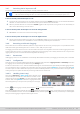
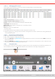
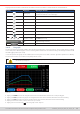
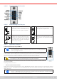
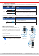
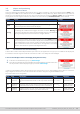
Table Of Contents
- 1. General
- 1.1 About this document
- 1.2 Warranty
- 1.3 Limitation of liability
- 1.4 Disposal of equipment
- 1.5 Product key
- 1.6 Intended usage
- 1.7 Safety
- 1.8 Technical Data
- 1.9 Construction and function
- 1.9.1 General description
- 1.9.2 Block diagram
- 1.9.3 Scope of delivery
- 1.9.4 Accessories
- 1.9.5 Options
- 1.9.6 The control panel (HMI)
- 1.9.7 USB port (rear side)
- 1.9.8 Interface module slot
- 1.9.9 Analog interface
- 1.9.10 “Share BUS” connector
- 1.9.11 “Sense” connector (remote sensing)
- 1.9.12 Master-Slave bus
- 1.9.13 Ethernet port
- 2. Installation & commissioning
- 2.1 Transport and storage
- 2.2 Unpacking and visual check
- 2.3 Installation
- 2.3.1 Safety procedures before installation and use
- 2.3.2 Preparation
- 2.3.3 Installing the device
- 2.3.4 Connection to AC supply
- 2.3.5 Connection to DC sources
- 2.3.6 Connection of remote sensing
- 2.3.7 Grounding of the DC terminal
- 2.3.8 Installation of an interface module
- 2.3.9 Connection of the analog interface
- 2.3.10 Connection of the Share bus
- 2.3.11 Connection of the USB port (rear side)
- 2.3.12 Initial commission
- 2.3.13 Commission after a firmware update or a long period of non-use
- 3. Operation and application
- 3.1 Important notes
- 3.2 Operating modes
- 3.3 Alarm conditions
- 3.4 Manual operation
- 3.5 Remote control
- 3.6 Alarms and monitoring
- 3.7 Locking the control panel (HMI)
- 3.8 Locking the adjustment limits and user profiles
- 3.9 Loading and saving user profiles
- 3.10 The function generator
- 3.10.1 Introduction
- 3.10.2 General
- 3.10.3 Method of operation
- 3.10.4 Manual operation
- 3.10.5 Sine wave function
- 3.10.6 Triangular function
- 3.10.7 Rectangular function
- 3.10.8 Trapezoidal function
- 3.10.9 DIN 40839 function
- 3.10.10 Arbitrary function
- 3.10.11 Ramp function
- 3.10.12 IU table function (XY table)
- 3.10.13 Battery test function
- 3.10.14 MPP tracking function
- 3.10.15 Remote control of the function generator
- 3.11 Other applications
- 4. Service and maintenance
- 5. Contact and support

© EA Elektro-Automatik in 2022, this information is subject to change without notice 5133200840_manual_elr_10000_2u_3kw_en_02
3.4.7 Switching the DC input on or o
The DC input of the device can be manually or remotely switched on and off.
Switching the DC input on during manual operation or digital remote control can be disabled by pin REM-
SB of the built-in analog interface. For more information refer to 3.4.3.1 and example a) in 3.5.4.7.
► How to manually switch the DC input on or off
1. As long as the control panel is not completely locked press the button On/Off. Otherwise you are asked to disable the
HMI lock. In case the HMI lock is connected to a PIN, you are asked to enter the PIN rst.
2. With the possible HMI lock removed, button On/Off toggles the DC input state, as long as this is not restricted by an
alarm or the device being in remote control.
► How to remotely switch the DC input on or off via the analog interface
1. See section
““3.5.4. Remote control via the analog interface”.
► How to remotely switch the DC input on or off via the digital interface
1. See the external documentation “Programming Guide ModBus & SCPI” if you are using custom software, or refer to the
external documentation from LabVIEW VIs or other software provided by the manufacturer.
3.4.8 Recording to USB stick (logging)
Device data can be recorded to USB stick (USB 3.0 is supported, but not all memory sizes) anytime. For specications of the
USB stick and the generated log les refer to section
“1.9.6.5. USB port (front side)”
.
The logging stores les of CSV format on the stick where the layout of the log data is the same as when logging via PC with
software EA Power Control. The advantage of USB logging over PC logging is the mobility and that no PC is required. The
logging feature just has to be activated and congured in the Settings.
3.4.8.1 Restrictions
USB logging in this form isn’t available or automatically deactivated if the battery test logging in the battery test is activated.
3.4.8.2 Conguration
Also see section
3.4.3.6
. After USB logging has been enabled and the parameters Logging interval and Start/Stop have been
set, logging can be started anytime after leaving the Settings menu.
Furthermore see section
3.4.3.1
. There are additional settings for the CSV le itself as generated by the USB logging features.
You can switch the column separator format between german/european standard (Default) or US american standard (US).
The other option is used to deactivate the physical unit that is added by default to every set/actual value in the log le. Deac-
tivating this option simplies the CSV le processing in MS Excel or similar tools.
3.4.8.3 Handling (start/stop)
With setting Start/stop to At DC on/off logging will start each
time the DC input of the device is switched on, no matter if man-
ually with the front button On/Off or remotely via analog or digital
interface. With setting Manual it’s different. Logging is then start-
ed and stopped only in the quick menu (see gure to the right).
Button starts logging manually and changed to , which is for manual stop.
Soon after logging has been started, the symbol indicates the ongoing logging action. In case there is an error while logging,
such as the USB stick is full or removed, it will be indicated by another symbol ( ). After every manual stop or switching the
DC input off the logging is stopped and the log le closed.