
Manual
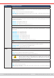
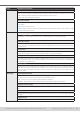
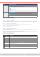
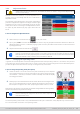
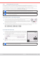
Table Of Contents
- 1. General
- 1.1 About this document
- 1.2 Warranty
- 1.3 Limitation of liability
- 1.4 Disposal of equipment
- 1.5 Product key
- 1.6 Intended usage
- 1.7 Safety
- 1.8 Technical Data
- 1.9 Construction and function
- 1.9.1 General description
- 1.9.2 Block diagram
- 1.9.3 Scope of delivery
- 1.9.4 Accessories
- 1.9.5 Options
- 1.9.6 The control panel (HMI)
- 1.9.7 USB port (rear side)
- 1.9.8 Interface module slot
- 1.9.9 Analog interface
- 1.9.10 “Share BUS” connector
- 1.9.11 “Sense” connector (remote sensing)
- 1.9.12 Master-Slave bus
- 1.9.13 Ethernet port
- 2. Installation & commissioning
- 2.1 Transport and storage
- 2.2 Unpacking and visual check
- 2.3 Installation
- 2.3.1 Safety procedures before installation and use
- 2.3.2 Preparation
- 2.3.3 Installing the device
- 2.3.4 Connection to AC supply
- 2.3.5 Connection to DC sources
- 2.3.6 Connection of remote sensing
- 2.3.7 Grounding of the DC terminal
- 2.3.8 Installation of an interface module
- 2.3.9 Connection of the analog interface
- 2.3.10 Connection of the Share bus
- 2.3.11 Connection of the USB port (rear side)
- 2.3.12 Initial commission
- 2.3.13 Commission after a firmware update or a long period of non-use
- 3. Operation and application
- 3.1 Important notes
- 3.2 Operating modes
- 3.3 Alarm conditions
- 3.4 Manual operation
- 3.5 Remote control
- 3.6 Alarms and monitoring
- 3.7 Locking the control panel (HMI)
- 3.8 Locking the adjustment limits and user profiles
- 3.9 Loading and saving user profiles
- 3.10 The function generator
- 3.10.1 Introduction
- 3.10.2 General
- 3.10.3 Method of operation
- 3.10.4 Manual operation
- 3.10.5 Sine wave function
- 3.10.6 Triangular function
- 3.10.7 Rectangular function
- 3.10.8 Trapezoidal function
- 3.10.9 DIN 40839 function
- 3.10.10 Arbitrary function
- 3.10.11 Ramp function
- 3.10.12 IU table function (XY table)
- 3.10.13 Battery test function
- 3.10.14 MPP tracking function
- 3.10.15 Remote control of the function generator
- 3.11 Other applications
- 4. Service and maintenance
- 5. Contact and support

© EA Elektro-Automatik in 2022, this information is subject to change without notice 5033200840_manual_elr_10000_2u_3kw_en_02
3.4.6 Manual adjustment of set values
The set values for voltage, current and power are the fundamental operating possibilities of a power supply and hence the
two rotary knobs on the front of the device are always assigned to two of the values in manual operation.
The resistance value is connected to the “R mode” which has to be activated separately, for instance via the quick menu. Refer
to
“3.4.3. Conguration via the menu”
as well as
“3.2.4. Resistance regulation / constant resistance”
for details.
Set values can be entered manually in two ways, via rotary knob or direct input. While the rotary knobs adjust values con-
tinuously, entering them via numeric pad can be used to change values in bigger steps.
Changing a value is immediately submitted, no matter if the DC input is switched on or off.
When adjusting set values, upper and lower limits may come into effect. See section “3.4.4. Adjustment
limits”. Once a limit is reached, the display will show a small note like “Limit: U-max” etc. for a short time
in proximity to the adjusted value.
► How to adjust set values U, I, P or R with the rotary knobs
1. First check if the value you want to change is already assigned to one of the rotary knobs. The
main screen displays the assignment as depicted in the gure to the right.
2. If, as shown in the example, the assignment is voltage (U, left knob) and current (I, right knob),
and it’s required to set the power, then the assignment of the right-hand knob can be changed
by tapping on its depiction until it shows “P”. In the left-hand display area the set values of
power would then be shown as selected.
3. After successful selection, the desired value can be set within the dened limits. Selecting the next digit is done by
pushing the rotary knob which shifts the cursor from right to left (selected digit will be underlined):
► How to adjust values via direct input:
1. In the main screen, depending on the rotary knob assignment, values can be set
for voltage (U), current (I), power (P) or resistance (R) via direct input by tapping
on one of the small ten-key pad symbols, for example the one in the blue area if
you wanted to adjust the voltage.
2. Enter the required value using the ten-key pad. Similar to a pocket calculator
the key clears the input. Decimal values are set by tapping the
point key. For example, 54.3 V is entered with and
.
3. Unless the new values isn’t rejected for some reason, the display would then
switch back to the main page and the set value would be submitted to the DC
input.
Upon entering a value which exceeds the corresponding limit, a note would pop up, the value in the frame
reset to 0 and not be accepted and submitted.