
Manual
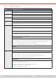
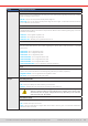
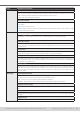
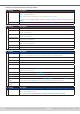
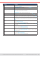
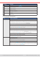
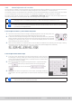
Table Of Contents
- 1. General
- 1.1 About this document
- 1.2 Warranty
- 1.3 Limitation of liability
- 1.4 Disposal of equipment
- 1.5 Product key
- 1.6 Intended usage
- 1.7 Safety
- 1.8 Technical Data
- 1.9 Construction and function
- 1.9.1 General description
- 1.9.2 Block diagram
- 1.9.3 Scope of delivery
- 1.9.4 Accessories
- 1.9.5 Options
- 1.9.6 The control panel (HMI)
- 1.9.7 USB port (rear side)
- 1.9.8 Interface module slot
- 1.9.9 Analog interface
- 1.9.10 “Share BUS” connector
- 1.9.11 “Sense” connector (remote sensing)
- 1.9.12 Master-Slave bus
- 1.9.13 Ethernet port
- 2. Installation & commissioning
- 2.1 Transport and storage
- 2.2 Unpacking and visual check
- 2.3 Installation
- 2.3.1 Safety procedures before installation and use
- 2.3.2 Preparation
- 2.3.3 Installing the device
- 2.3.4 Connection to AC supply
- 2.3.5 Connection to DC sources
- 2.3.6 Connection of remote sensing
- 2.3.7 Grounding of the DC terminal
- 2.3.8 Installation of an interface module
- 2.3.9 Connection of the analog interface
- 2.3.10 Connection of the Share bus
- 2.3.11 Connection of the USB port (rear side)
- 2.3.12 Initial commission
- 2.3.13 Commission after a firmware update or a long period of non-use
- 3. Operation and application
- 3.1 Important notes
- 3.2 Operating modes
- 3.3 Alarm conditions
- 3.4 Manual operation
- 3.5 Remote control
- 3.6 Alarms and monitoring
- 3.7 Locking the control panel (HMI)
- 3.8 Locking the adjustment limits and user profiles
- 3.9 Loading and saving user profiles
- 3.10 The function generator
- 3.10.1 Introduction
- 3.10.2 General
- 3.10.3 Method of operation
- 3.10.4 Manual operation
- 3.10.5 Sine wave function
- 3.10.6 Triangular function
- 3.10.7 Rectangular function
- 3.10.8 Trapezoidal function
- 3.10.9 DIN 40839 function
- 3.10.10 Arbitrary function
- 3.10.11 Ramp function
- 3.10.12 IU table function (XY table)
- 3.10.13 Battery test function
- 3.10.14 MPP tracking function
- 3.10.15 Remote control of the function generator
- 3.11 Other applications
- 4. Service and maintenance
- 5. Contact and support

© EA Elektro-Automatik in 2022, this information is subject to change without notice 4733200840_manual_elr_10000_2u_3kw_en_02
IF Settings Description
Pronet/IO (1 & 2 Port)
Host name Free choice of host name (default: Client)
Domain name Free choice of Domain (default: Workgroup)
Function Tag String input box for a user-denable text which describes the Pronet slave function tag. Max.
length: 32 characters
Location Tag String input box for a user-denable text which describes the Pronet slave location tag. Max.
length: 22 characters
Installation Date String input box for a user-denable text which describes the Probus slave installation date tag.
Max. length: 40 characters
Description String input box for a user-denable text which describes the Probus slave. Max. length: 54
characters
Station Name String input box for a user-denable text which describes the Pronet station name. Max. length:
200 characters
Further communication related parameters
Group Parameters & description
Timeouts
TCP keep-alive (internal) / TCP keep-alive (slot)
Activates/deactivates keep-alive network functionality for the internal Ethernet port and for an a
standard Ethernet module (IF-AB-ETHxx), if installed in the slot. The “keep-alive” network packets
are used to keep the socket connection open. As long as keep-alive is valid in the network, the
device will disable the Ethernet timeout. Also see below at Timeout ETH.
Timeout USB/RS232
Denes the max. time between two subsequent bytes or blocks of a transferred message. For more
information about the timeout refer to the external programming documentation “Programming
ModBus & SCPI”. Default value: 5 ms, Range: 5...65535
Timeout ETH (internal) / Timeout ETH (slot)
Denes a timeout after which the device would close the socket connection if there was no com-
mand communication between the controlling unit (PC, PLC etc.) and the device for the adjusted
time. The timeout is ineffective as long as option TCP keep-alive is enabled for the particular
interface and the keep-alive network service is running. A setting of 0 would deactivate the timeout
permanently. Default value: 5 s, Range: 0 / 5...65535 (0 = timeout deactivated)
Interface monitoring / Timeout Interface monitoring
Activates/deactivates the interface monitoring (see section
“3.5.3.3. Interface monitoring”
).
Default values: off, 5 s / Range: 5..65535
Protocols
Communication protocols
Enables or disables SCPI or ModBus communication protocols for the device. The change is im-
mediately effective. Only one of both can be disabled.
ModBus specication compliance
Allows to switch from Limited (default setting) to Full which makes the device send messages in
ModBus RTU or ModBus TCP format which fully comply to the specication and are compatible to
softwares available on the market. With Limited the device would still use the old, partially wrong
message format (see programming guide for details).