
Manual
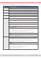
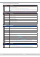
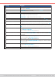
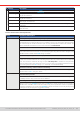
Table Of Contents
- 1. General
- 1.1 About this document
- 1.2 Warranty
- 1.3 Limitation of liability
- 1.4 Disposal of equipment
- 1.5 Product key
- 1.6 Intended usage
- 1.7 Safety
- 1.8 Technical Data
- 1.9 Construction and function
- 1.9.1 General description
- 1.9.2 Block diagram
- 1.9.3 Scope of delivery
- 1.9.4 Accessories
- 1.9.5 Options
- 1.9.6 The control panel (HMI)
- 1.9.7 USB port (rear side)
- 1.9.8 Interface module slot
- 1.9.9 Analog interface
- 1.9.10 “Share BUS” connector
- 1.9.11 “Sense” connector (remote sensing)
- 1.9.12 Master-Slave bus
- 1.9.13 Ethernet port
- 2. Installation & commissioning
- 2.1 Transport and storage
- 2.2 Unpacking and visual check
- 2.3 Installation
- 2.3.1 Safety procedures before installation and use
- 2.3.2 Preparation
- 2.3.3 Installing the device
- 2.3.4 Connection to AC supply
- 2.3.5 Connection to DC sources
- 2.3.6 Connection of remote sensing
- 2.3.7 Grounding of the DC terminal
- 2.3.8 Installation of an interface module
- 2.3.9 Connection of the analog interface
- 2.3.10 Connection of the Share bus
- 2.3.11 Connection of the USB port (rear side)
- 2.3.12 Initial commission
- 2.3.13 Commission after a firmware update or a long period of non-use
- 3. Operation and application
- 3.1 Important notes
- 3.2 Operating modes
- 3.3 Alarm conditions
- 3.4 Manual operation
- 3.5 Remote control
- 3.6 Alarms and monitoring
- 3.7 Locking the control panel (HMI)
- 3.8 Locking the adjustment limits and user profiles
- 3.9 Loading and saving user profiles
- 3.10 The function generator
- 3.10.1 Introduction
- 3.10.2 General
- 3.10.3 Method of operation
- 3.10.4 Manual operation
- 3.10.5 Sine wave function
- 3.10.6 Triangular function
- 3.10.7 Rectangular function
- 3.10.8 Trapezoidal function
- 3.10.9 DIN 40839 function
- 3.10.10 Arbitrary function
- 3.10.11 Ramp function
- 3.10.12 IU table function (XY table)
- 3.10.13 Battery test function
- 3.10.14 MPP tracking function
- 3.10.15 Remote control of the function generator
- 3.11 Other applications
- 4. Service and maintenance
- 5. Contact and support

© EA Elektro-Automatik in 2022, this information is subject to change without notice 4633200840_manual_elr_10000_2u_3kw_en_02
IF Settings Description
CAN
Baud rate Setup of the CAN bus speed or baud rate in typical value between 10 kbps and
1Mbps. Default: 500 kbps
ID Format Selection of the CAN ID format and range between Standard (11 Bit ID, 0h...7ffh)
and Extended (29 Bit, 0h...1fffffffh)
Bus termination Activates or deactivates CAN bus termination with a built-in resistor. Default: off
Data length Determines the DLC (data length) of all messages sent from the device.
Auto = length can vary between 3 and 8 bytes
Always 8 Bytes = length is always 8, lled up with zeros
Base ID Setup of the CAN base ID (11 Bit or 29 Bit, hex format). Default: 0h
Broadcast ID Setup of the CAN broadcast ID (11 Bit or 29 Bit, hex format). Default: 7ffh
Base ID Cyclic Read Setup of the CAN base ID (11 Bit or 29 Bit, hex format) for cyclic read of several
object groups. The device will automatically send object data to the IDs dened with
this setting. For more information refer to the programming guide. Default: 100h
Base ID Cyclic Send Setup of the CAN base ID (11 Bit or 29 Bit, hex format) for cyclic send of set values
along with status. For more information refer to the programming guide. Default:
200h
Cyclic Read Time: Status Activation/deactivation and time setting for the cyclic read of status from the
adjusted Base ID Cyclic Read
Range: 20...5000 ms. Default: 0 ms (deactivated)
Cyclic Read Time: Set values Activation/deactivation and time setting for the cyclic read of set values of U & I
from the adjusted Base ID Cyclic Read + 2. Range: 20...5000 ms. Default: 0 ms
(deactivated)
Cyclic Read Time: Limit values 1 Activation/deactivation and time setting for the cyclic read of adjustment limits of
U & I from the adjusted Base ID Cyclic Read + 3.
Range: 20...5000 ms. Default: 0 ms (deactivated)
Cyclic Read Time: Limit values 2 Activation/deactivation and time setting for the cyclic read of adjustment limits
of P & R to the adjusted Base ID Cyclic Read + 4. Range: 20...5000 ms. Default:
0 ms (deactivated)
Cyclic Read Time: Actual values Activation/deactivation and time setting for the cyclic read of actual values from
the adjusted Base ID Cyclic Read + 1
Range: 20...5000 ms. Default: 0 ms (deactivated)
Module rmware CAN module rmware version