
Manual
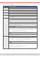
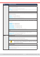
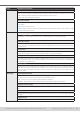
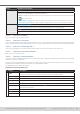
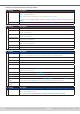
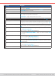
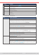
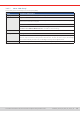
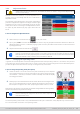
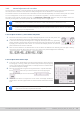
Table Of Contents
- 1. General
- 1.1 About this document
- 1.2 Warranty
- 1.3 Limitation of liability
- 1.4 Disposal of equipment
- 1.5 Product key
- 1.6 Intended usage
- 1.7 Safety
- 1.8 Technical Data
- 1.9 Construction and function
- 1.9.1 General description
- 1.9.2 Block diagram
- 1.9.3 Scope of delivery
- 1.9.4 Accessories
- 1.9.5 Options
- 1.9.6 The control panel (HMI)
- 1.9.7 USB port (rear side)
- 1.9.8 Interface module slot
- 1.9.9 Analog interface
- 1.9.10 “Share BUS” connector
- 1.9.11 “Sense” connector (remote sensing)
- 1.9.12 Master-Slave bus
- 1.9.13 Ethernet port
- 2. Installation & commissioning
- 2.1 Transport and storage
- 2.2 Unpacking and visual check
- 2.3 Installation
- 2.3.1 Safety procedures before installation and use
- 2.3.2 Preparation
- 2.3.3 Installing the device
- 2.3.4 Connection to AC supply
- 2.3.5 Connection to DC sources
- 2.3.6 Connection of remote sensing
- 2.3.7 Grounding of the DC terminal
- 2.3.8 Installation of an interface module
- 2.3.9 Connection of the analog interface
- 2.3.10 Connection of the Share bus
- 2.3.11 Connection of the USB port (rear side)
- 2.3.12 Initial commission
- 2.3.13 Commission after a firmware update or a long period of non-use
- 3. Operation and application
- 3.1 Important notes
- 3.2 Operating modes
- 3.3 Alarm conditions
- 3.4 Manual operation
- 3.5 Remote control
- 3.6 Alarms and monitoring
- 3.7 Locking the control panel (HMI)
- 3.8 Locking the adjustment limits and user profiles
- 3.9 Loading and saving user profiles
- 3.10 The function generator
- 3.10.1 Introduction
- 3.10.2 General
- 3.10.3 Method of operation
- 3.10.4 Manual operation
- 3.10.5 Sine wave function
- 3.10.6 Triangular function
- 3.10.7 Rectangular function
- 3.10.8 Trapezoidal function
- 3.10.9 DIN 40839 function
- 3.10.10 Arbitrary function
- 3.10.11 Ramp function
- 3.10.12 IU table function (XY table)
- 3.10.13 Battery test function
- 3.10.14 MPP tracking function
- 3.10.15 Remote control of the function generator
- 3.11 Other applications
- 4. Service and maintenance
- 5. Contact and support

© EA Elektro-Automatik in 2022, this information is subject to change without notice 4533200840_manual_elr_10000_2u_3kw_en_02
Settings for the optional interface modules (IF-AB-xxx)
IF Settings Description
CANopen
Baud Rate CAN bus baud rate selection that is used by the CANopen interface.
Auto = Automatic detection
LSS = Baud rate and node address are assigned by the bus master
Fixed baud rates: 10 kbps, 20 kbps, 50 kbps, 100 kbps, 125 kbps, 250 kbps, 500 kbps, 800 kbps,
1Mbps
Node Address Selection of the CANopen node address in the range 1...127
IF Settings Description
Probus
Node Address
Selection of the Probus or node address of the device within range 1...125 via direct input
Function Tag
String input box for a user-denable text which describes the Probus slave function tag. Max.
length: 32 characters
Location Tag
String input box for a user-denable text which describes the Probus slave location tag. Max.
length: 22 characters
Installation Date
String input box for a user-denable text which describes the Probus slave installation date tag.
Max. length: 40 characters
Description
String input box for a user-denable text which describes the Probus slave.
Max. length: 54 characters
Manufacturer ID
Registered manufacturer ID with the Probus organization
Ident number
Product identication number, same as in the GSD le
IF Settings Description
Slot Ethernet / ModBus-TCP (1 & 2 Port)
DHCP The IF allows a DHCP server to allocate an IP address, a subnet mask and a gateway. If no DHCP
server is in the network then network parameters will be set as dened below.
IP address This option is activated by default. An IP address can be manually allocated.
Subnet mask Here a subnet mask can be dened if the default subnet mask is not suitable.
Gateway Here a gateway address can be allocated if required..
DNS address Here the addresses of the rst and second Domain Name Servers (DNS) can be dened, if needed.
Port Range: 0...65535, default port: 5025 = Modbus RTU
Reserved ports: 502, 537
Host name User denable host name (default: Client)
Domain User denable domain (default: Workgroup)
MAC address of the internal Ethernet port
Speed / Duplex
Port 1
Manual selection of transmission speed (10MBit/100MBit) and duplex mode (full/half). It’s rec-
ommended to use the Auto option and only revert to another option if Auto fails.
Speed / Duplex
Port 2
Different Ethernet port settings for 2-port modules are possible, as these include an Ethernet switch
IF Settings Description
RS232
Baud rate
The baud rate is selectable, other serial settings can’t be changed and are dened like this: 8 data
bits, 1 stop bit, parity = none
Baud rates: 2400Bd, 4800Bd, 9600Bd, 19200Bd, 38400Bd, 57600Bd, 115200Bd