
Manual
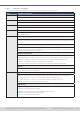
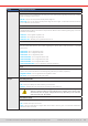
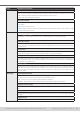
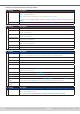
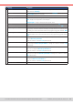
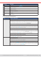
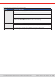
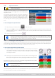
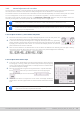
Table Of Contents
- 1. General
- 1.1 About this document
- 1.2 Warranty
- 1.3 Limitation of liability
- 1.4 Disposal of equipment
- 1.5 Product key
- 1.6 Intended usage
- 1.7 Safety
- 1.8 Technical Data
- 1.9 Construction and function
- 1.9.1 General description
- 1.9.2 Block diagram
- 1.9.3 Scope of delivery
- 1.9.4 Accessories
- 1.9.5 Options
- 1.9.6 The control panel (HMI)
- 1.9.7 USB port (rear side)
- 1.9.8 Interface module slot
- 1.9.9 Analog interface
- 1.9.10 “Share BUS” connector
- 1.9.11 “Sense” connector (remote sensing)
- 1.9.12 Master-Slave bus
- 1.9.13 Ethernet port
- 2. Installation & commissioning
- 2.1 Transport and storage
- 2.2 Unpacking and visual check
- 2.3 Installation
- 2.3.1 Safety procedures before installation and use
- 2.3.2 Preparation
- 2.3.3 Installing the device
- 2.3.4 Connection to AC supply
- 2.3.5 Connection to DC sources
- 2.3.6 Connection of remote sensing
- 2.3.7 Grounding of the DC terminal
- 2.3.8 Installation of an interface module
- 2.3.9 Connection of the analog interface
- 2.3.10 Connection of the Share bus
- 2.3.11 Connection of the USB port (rear side)
- 2.3.12 Initial commission
- 2.3.13 Commission after a firmware update or a long period of non-use
- 3. Operation and application
- 3.1 Important notes
- 3.2 Operating modes
- 3.3 Alarm conditions
- 3.4 Manual operation
- 3.5 Remote control
- 3.6 Alarms and monitoring
- 3.7 Locking the control panel (HMI)
- 3.8 Locking the adjustment limits and user profiles
- 3.9 Loading and saving user profiles
- 3.10 The function generator
- 3.10.1 Introduction
- 3.10.2 General
- 3.10.3 Method of operation
- 3.10.4 Manual operation
- 3.10.5 Sine wave function
- 3.10.6 Triangular function
- 3.10.7 Rectangular function
- 3.10.8 Trapezoidal function
- 3.10.9 DIN 40839 function
- 3.10.10 Arbitrary function
- 3.10.11 Ramp function
- 3.10.12 IU table function (XY table)
- 3.10.13 Battery test function
- 3.10.14 MPP tracking function
- 3.10.15 Remote control of the function generator
- 3.11 Other applications
- 4. Service and maintenance
- 5. Contact and support

© EA Elektro-Automatik in 2022, this information is subject to change without notice 4433200840_manual_elr_10000_2u_3kw_en_02
Group Parameters & description
USB logging Start/stop
Denes how the USB logging is started and stopped.
• Manual = Logging only starts and stops upon user interaction on the HMI, by accessing touch button
in the quick menu.
• At DC on/off = Logging starts and stops with every change of state on the DC input, no matter if
caused by the user, software or a device alarm. Attention: Every next start will create a new log le.
Reset / Restart Reset device to defaults
This touch area will initiate a reset of all settings (HMI, prole etc.) to factory default.
Restart
Triggers a warm start
3.4.3.2 Sub menu “Proles”
See
“3.9. Loading and saving user proles”.
3.4.3.3 Sub menu “Overview”
This menu page displays an overview of the set values (U, I, P or U, I, P, R), device alarm thresholds, event settings, adjustment
limits, as well as an alarm history which lists the number of device alarms that occurred since the device has been powered.
3.4.3.4 Sub menu “About HW, SW, ...”
This menu page displays an overview of device relevant data such as serial number, article number etc.
3.4.3.5 Sub menu “Function Generator”
See “3.10. The function generator”.
3.4.3.6 Sub menu “Communication”
This sub menu offers settings for digital communication via the built-in interfaces USB and Ethernet and also for the optional
interface modules of IF-AB series.
There are furthermore adjustable communication timeouts. For more information about these timeout refer to the external,
on USB stick included documentation “Programming guide ModBus & SCPI”.
The USB itself doesn’t require any settings.
Settings for the internal Ethernet port
IF Settings Description
Ethernet (internal)
DHCP
The IF allows a DHCP server to allocate an IP address, a subnet mask and a gateway. If no DHCP
server is in the network then network parameters will be set as dened below.
IP address
Manually allocate an IP address.
Subnet mask
Manually allocate a subnet mask.
Gateway
Manually allocate a gateway address, if required.
DNS address
Manually allocate addresses of a Domain Name Server (DNS), if required.
Port
Select port in the range 0...65535. Default: 5025
Reserved ports: 502, 537
Host name
User denable host name
Domain
User denable domain
MAC address
of the internal Ethernet port