
Manual
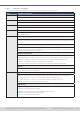
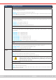
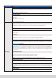
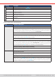
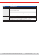
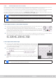
Table Of Contents
- 1. General
- 1.1 About this document
- 1.2 Warranty
- 1.3 Limitation of liability
- 1.4 Disposal of equipment
- 1.5 Product key
- 1.6 Intended usage
- 1.7 Safety
- 1.8 Technical Data
- 1.9 Construction and function
- 1.9.1 General description
- 1.9.2 Block diagram
- 1.9.3 Scope of delivery
- 1.9.4 Accessories
- 1.9.5 Options
- 1.9.6 The control panel (HMI)
- 1.9.7 USB port (rear side)
- 1.9.8 Interface module slot
- 1.9.9 Analog interface
- 1.9.10 “Share BUS” connector
- 1.9.11 “Sense” connector (remote sensing)
- 1.9.12 Master-Slave bus
- 1.9.13 Ethernet port
- 2. Installation & commissioning
- 2.1 Transport and storage
- 2.2 Unpacking and visual check
- 2.3 Installation
- 2.3.1 Safety procedures before installation and use
- 2.3.2 Preparation
- 2.3.3 Installing the device
- 2.3.4 Connection to AC supply
- 2.3.5 Connection to DC sources
- 2.3.6 Connection of remote sensing
- 2.3.7 Grounding of the DC terminal
- 2.3.8 Installation of an interface module
- 2.3.9 Connection of the analog interface
- 2.3.10 Connection of the Share bus
- 2.3.11 Connection of the USB port (rear side)
- 2.3.12 Initial commission
- 2.3.13 Commission after a firmware update or a long period of non-use
- 3. Operation and application
- 3.1 Important notes
- 3.2 Operating modes
- 3.3 Alarm conditions
- 3.4 Manual operation
- 3.5 Remote control
- 3.6 Alarms and monitoring
- 3.7 Locking the control panel (HMI)
- 3.8 Locking the adjustment limits and user profiles
- 3.9 Loading and saving user profiles
- 3.10 The function generator
- 3.10.1 Introduction
- 3.10.2 General
- 3.10.3 Method of operation
- 3.10.4 Manual operation
- 3.10.5 Sine wave function
- 3.10.6 Triangular function
- 3.10.7 Rectangular function
- 3.10.8 Trapezoidal function
- 3.10.9 DIN 40839 function
- 3.10.10 Arbitrary function
- 3.10.11 Ramp function
- 3.10.12 IU table function (XY table)
- 3.10.13 Battery test function
- 3.10.14 MPP tracking function
- 3.10.15 Remote control of the function generator
- 3.11 Other applications
- 4. Service and maintenance
- 5. Contact and support

© EA Elektro-Automatik in 2022, this information is subject to change without notice 4333200840_manual_elr_10000_2u_3kw_en_02
Group Parameters & description
DC input State
after remote
Determines the condition of the DC input after leaving remote control either manually or by command:
• Off = Default, DC input will always be off after leaving remote control
• Auto = DC input will keep the last state
State
after OT alarm
Determines the condition of the DC input after an overtemperature (OT) alarm, once the device has
cooled down:
• Off = DC input will remain off
• Auto = Default, the device will automatically restore the situation before the OT alarm, which usually
means the DC input to be on
Master-slave Mode
Selecting Master or Slave enables the master-slave mode (MS) and denes the position for the unit in
the MS system. For details see section
“3.11.1. Parallel operation in master-slave (MS)””
.
Termination resistor
Activates or deactivates the so-called bus termination of the digital master-slave bus via a switchable
resistor. Termination should be activated if required, usually when problems with the master-slave bus
operation occur.
Bias resistors
Additionally to the regular termination resistor (TERM) this activates two bias resistor, if required, to help
stabilize the bus further. Tap on the information symbol for a graphical depiction.
Backlight off after 60s
If activated, it will switch off the display’s backlight after 60 seconds of inactivity. This settings is pri-
marily intended for slave units where the display isn’t supposed to be permanently on. It’s identical to
the setting in menu “HMI setup”.
Initialize system
Tapping this touch area will repeat the initialization of the master-slave system in case the detection
of all slave units by the master was unsuccessful, so the system would have less total power than ex-
pected, or has to be repeated manually in case the master unit couldn’t detect a missing slave or one
slave has failed.
USB logging Log le separator format
Denes the format of CSV les generated from logging les (also see
1.9.6.5
and
3.4.8
). This setting
also affects other features where a CSV le can be loaded or saved.
• US = Comma as column separator (US standard for CSV les)
• Default = Semicolon as column separator (german/european standard for CSV les)
Logging with units (V,A,W)
CSV les generated from USB logging by default add physical units to values. This can be deactivated
here.
USB logging
Activates/deactivates logging to USB stick. For more information refer to
“3.4.8. Recording to USB stick
(logging)”
.
Logging interval
Denes the time between two records in the log le. Selection: 500 ms, 1 s, 2 s, 5 s