
Manual
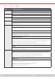
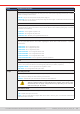
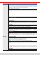
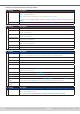
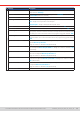
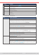
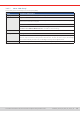
Table Of Contents
- 1. General
- 1.1 About this document
- 1.2 Warranty
- 1.3 Limitation of liability
- 1.4 Disposal of equipment
- 1.5 Product key
- 1.6 Intended usage
- 1.7 Safety
- 1.8 Technical Data
- 1.9 Construction and function
- 1.9.1 General description
- 1.9.2 Block diagram
- 1.9.3 Scope of delivery
- 1.9.4 Accessories
- 1.9.5 Options
- 1.9.6 The control panel (HMI)
- 1.9.7 USB port (rear side)
- 1.9.8 Interface module slot
- 1.9.9 Analog interface
- 1.9.10 “Share BUS” connector
- 1.9.11 “Sense” connector (remote sensing)
- 1.9.12 Master-Slave bus
- 1.9.13 Ethernet port
- 2. Installation & commissioning
- 2.1 Transport and storage
- 2.2 Unpacking and visual check
- 2.3 Installation
- 2.3.1 Safety procedures before installation and use
- 2.3.2 Preparation
- 2.3.3 Installing the device
- 2.3.4 Connection to AC supply
- 2.3.5 Connection to DC sources
- 2.3.6 Connection of remote sensing
- 2.3.7 Grounding of the DC terminal
- 2.3.8 Installation of an interface module
- 2.3.9 Connection of the analog interface
- 2.3.10 Connection of the Share bus
- 2.3.11 Connection of the USB port (rear side)
- 2.3.12 Initial commission
- 2.3.13 Commission after a firmware update or a long period of non-use
- 3. Operation and application
- 3.1 Important notes
- 3.2 Operating modes
- 3.3 Alarm conditions
- 3.4 Manual operation
- 3.5 Remote control
- 3.6 Alarms and monitoring
- 3.7 Locking the control panel (HMI)
- 3.8 Locking the adjustment limits and user profiles
- 3.9 Loading and saving user profiles
- 3.10 The function generator
- 3.10.1 Introduction
- 3.10.2 General
- 3.10.3 Method of operation
- 3.10.4 Manual operation
- 3.10.5 Sine wave function
- 3.10.6 Triangular function
- 3.10.7 Rectangular function
- 3.10.8 Trapezoidal function
- 3.10.9 DIN 40839 function
- 3.10.10 Arbitrary function
- 3.10.11 Ramp function
- 3.10.12 IU table function (XY table)
- 3.10.13 Battery test function
- 3.10.14 MPP tracking function
- 3.10.15 Remote control of the function generator
- 3.11 Other applications
- 4. Service and maintenance
- 5. Contact and support

© EA Elektro-Automatik in 2022, this information is subject to change without notice 4233200840_manual_elr_10000_2u_3kw_en_02
Group Parameters & description
Analog interface REM-SB Action
Selects how the input pin REM-SB of the analog interface shall operate regarding the DC input condition
outside of analog remote control:
• DC Off = the pin can only switch the DC power stage off
• DC On/Off = the pin can switch the DC power stage off and on again, if it has been switched on before
from a different control location
Pin 6
Pin 6 of the analog interface (see section
“3.5.4.3. Analog interface specication”
) is by default assigned
to signal both device alarms OT and PF. This parameter allows to also enable signaling only one of both
(3 possible combinations):
• Alarm OT = Pin 6 signals only alarm OT
• Alarm PF = Pin 6 signals only alarm PF
• Alarm PF + OT = Default, pin 6 signals either PF or OT
Pin 14
Pin 14 of the analog interface (see section
3.5.4.3
) is by default assigned to only signal the device alarm
OVP. This parameter allows to also enable signaling the device alarms OCP and OPP in 7 possible
combinations:
• Alarm OVP = Pin 14 signals only OVP
• Alarm OCP = Pin 14 signals only OCP
• Alarm OPP = Pin 14 signals only OPP
• Alarm OVP+OCP = Pin 14 signals OVP or OCP
• Alarm OVP+OPP = Pin 14 signals OVP or OPP
• Alarm OCP+OPP = Pin 14 signals OCP or OPP
• Alarm OVP+OCP+OPP = Pin 14 signals any of the three alarms
Pin 15
Pin 15 of the analog interface (see section
3.5.4.3
) is by default assigned to only signal the regulation
mode CV. This parameter allows to enable signaling the DC input status (2 options):
• Regulation mode = Pin 15 signals the CV regulation mode
• DC status = Pin 15 signals the DC input status
DC input State after power ON
Determines the condition of the DC input after power-up.
• Off = DC input is always off after switching on the device
• Restore = Default, DC input state will be restored from last switch-off
The factory default of this setting, also after a device reset, is “Off”. Setting this to
“Restore” solely lies within the responsibility of the operator, as the device could
automatically start to supply voltage after boot-up, depending on the restored
state of the DC input. Be careful!
State
after PF alarm
Determines the condition of the DC input after a power fail (PF) alarm:
• Off = Default, DC input remains off
• Auto = DC input will switch on again after the PF alarm cause is gone, if it has been switched on
before the alarm occurred