
Manual
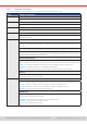
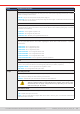
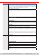
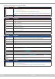
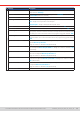
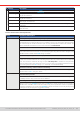
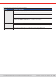
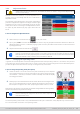
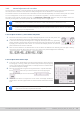
Table Of Contents
- 1. General
- 1.1 About this document
- 1.2 Warranty
- 1.3 Limitation of liability
- 1.4 Disposal of equipment
- 1.5 Product key
- 1.6 Intended usage
- 1.7 Safety
- 1.8 Technical Data
- 1.9 Construction and function
- 1.9.1 General description
- 1.9.2 Block diagram
- 1.9.3 Scope of delivery
- 1.9.4 Accessories
- 1.9.5 Options
- 1.9.6 The control panel (HMI)
- 1.9.7 USB port (rear side)
- 1.9.8 Interface module slot
- 1.9.9 Analog interface
- 1.9.10 “Share BUS” connector
- 1.9.11 “Sense” connector (remote sensing)
- 1.9.12 Master-Slave bus
- 1.9.13 Ethernet port
- 2. Installation & commissioning
- 2.1 Transport and storage
- 2.2 Unpacking and visual check
- 2.3 Installation
- 2.3.1 Safety procedures before installation and use
- 2.3.2 Preparation
- 2.3.3 Installing the device
- 2.3.4 Connection to AC supply
- 2.3.5 Connection to DC sources
- 2.3.6 Connection of remote sensing
- 2.3.7 Grounding of the DC terminal
- 2.3.8 Installation of an interface module
- 2.3.9 Connection of the analog interface
- 2.3.10 Connection of the Share bus
- 2.3.11 Connection of the USB port (rear side)
- 2.3.12 Initial commission
- 2.3.13 Commission after a firmware update or a long period of non-use
- 3. Operation and application
- 3.1 Important notes
- 3.2 Operating modes
- 3.3 Alarm conditions
- 3.4 Manual operation
- 3.5 Remote control
- 3.6 Alarms and monitoring
- 3.7 Locking the control panel (HMI)
- 3.8 Locking the adjustment limits and user profiles
- 3.9 Loading and saving user profiles
- 3.10 The function generator
- 3.10.1 Introduction
- 3.10.2 General
- 3.10.3 Method of operation
- 3.10.4 Manual operation
- 3.10.5 Sine wave function
- 3.10.6 Triangular function
- 3.10.7 Rectangular function
- 3.10.8 Trapezoidal function
- 3.10.9 DIN 40839 function
- 3.10.10 Arbitrary function
- 3.10.11 Ramp function
- 3.10.12 IU table function (XY table)
- 3.10.13 Battery test function
- 3.10.14 MPP tracking function
- 3.10.15 Remote control of the function generator
- 3.11 Other applications
- 4. Service and maintenance
- 5. Contact and support

© EA Elektro-Automatik in 2022, this information is subject to change without notice 4133200840_manual_elr_10000_2u_3kw_en_02
3.4.3.1 Sub menu “Settings”
This sub menu can be accessed directly from the main screen by tapping the Settings button.
Group Parameters & description
Presets U, I, P, R
Presetting of all set values via on-screen numeric pad.
Protection OVP, O CP, OPP
Adjust the thresholds of the protections
Limits U-max, U-min etc.
Dene the adjustment limits (nd more information in
“3.4.4. Adjustment limits”
)
User events UVD, OVD etc.
Dene supervision thresholds which can trigger user dened events (nd more information in
“3.6.2.1.
User dened events”
)
General Allow remote control
If remote control is allowed, the device can’t be controlled remotely over either the digital or analog
interfaces. This situation will be shown as “Local” in the status area on the main display. Also see sec-
tion
1.9.6.1.
R mode
Activates or deactivates the internal resistance control. If activated, the resistance set value and actual
will be shown the main screen. For details refer to
“3.2.4. Resistance regulation / constant resistance”
and “3.4.6. Manual adjustment of set values”.
Voltage controller speed
This switch can be used to select the internal voltage controller speed which, as a result, impacts possible
system oscillation. For more information refer to
“3.2.5. Dynamic characteristics and stability criteria”
.
• Slow = the voltage controller will be a little slower, the oscillation tendency will decrease
• Normal = the voltage controller is on standard speed (Default)
• Fast = the voltage controller will be a little faster, the oscillation tendency will increase
SEMI F47
Activates or deactivates a feature called SEMI F47 which is related to the equally named standard. See
“3.11.3. SEMI F47”
for more information.
Analog interface Range
Selects the voltage range for the analog set values, actual values and reference voltage output.
• 0...5 V = Range is 0...100% for set /actual values, reference voltage will be 5 V
• 0...10 V = Range is 0...100% for set /actual values, reference voltage will be 10 V
Also see
“3.5.4. Remote control via the analog interface”
REM-SB Level
Selects how the input pin REM-SB of the analog interface shall be working regarding levels (see
“3.5.4.3.
Analog interface specication”
) and logic:
• Normal = Levels and function as described in the table in
3.5.4.3
• Inverted = Levels and function will be inverted
Also see
“3.5.4.7. Application examples”