
Manual
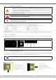
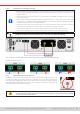
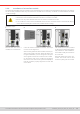
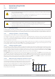

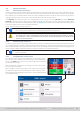
Table Of Contents
- 1. General
- 1.1 About this document
- 1.2 Warranty
- 1.3 Limitation of liability
- 1.4 Disposal of equipment
- 1.5 Product key
- 1.6 Intended usage
- 1.7 Safety
- 1.8 Technical Data
- 1.9 Construction and function
- 1.9.1 General description
- 1.9.2 Block diagram
- 1.9.3 Scope of delivery
- 1.9.4 Accessories
- 1.9.5 Options
- 1.9.6 The control panel (HMI)
- 1.9.7 USB port (rear side)
- 1.9.8 Interface module slot
- 1.9.9 Analog interface
- 1.9.10 “Share BUS” connector
- 1.9.11 “Sense” connector (remote sensing)
- 1.9.12 Master-Slave bus
- 1.9.13 Ethernet port
- 2. Installation & commissioning
- 2.1 Transport and storage
- 2.2 Unpacking and visual check
- 2.3 Installation
- 2.3.1 Safety procedures before installation and use
- 2.3.2 Preparation
- 2.3.3 Installing the device
- 2.3.4 Connection to AC supply
- 2.3.5 Connection to DC sources
- 2.3.6 Connection of remote sensing
- 2.3.7 Grounding of the DC terminal
- 2.3.8 Installation of an interface module
- 2.3.9 Connection of the analog interface
- 2.3.10 Connection of the Share bus
- 2.3.11 Connection of the USB port (rear side)
- 2.3.12 Initial commission
- 2.3.13 Commission after a firmware update or a long period of non-use
- 3. Operation and application
- 3.1 Important notes
- 3.2 Operating modes
- 3.3 Alarm conditions
- 3.4 Manual operation
- 3.5 Remote control
- 3.6 Alarms and monitoring
- 3.7 Locking the control panel (HMI)
- 3.8 Locking the adjustment limits and user profiles
- 3.9 Loading and saving user profiles
- 3.10 The function generator
- 3.10.1 Introduction
- 3.10.2 General
- 3.10.3 Method of operation
- 3.10.4 Manual operation
- 3.10.5 Sine wave function
- 3.10.6 Triangular function
- 3.10.7 Rectangular function
- 3.10.8 Trapezoidal function
- 3.10.9 DIN 40839 function
- 3.10.10 Arbitrary function
- 3.10.11 Ramp function
- 3.10.12 IU table function (XY table)
- 3.10.13 Battery test function
- 3.10.14 MPP tracking function
- 3.10.15 Remote control of the function generator
- 3.11 Other applications
- 4. Service and maintenance
- 5. Contact and support

© EA Elektro-Automatik in 2022, this information is subject to change without notice 4033200840_manual_elr_10000_2u_3kw_en_02
3.4 Manual operation
3. 4 .1 Switching on the device
The device should, as far as possible, always be switched on by putting the toggle switch on the front of the device to posi-
tion 1 (upper). Alternatively this can be done using an external cutout (contactor, circuit breaker) of suitable current capacity.
After switching on, the display will rst show some device related information (model, rmware versions etc.) and then a
language selection screen for 3 seconds. A few seconds later it will show the main screen.
In the Settings menu (also see section
“3.4.3. Conguration via the menu”)
in the group DC input is an option State after
power ON in which the user can determine the condition of the DC input after power-up. Factory setting here is Off, meaning
that the DC input will always be switched off after power-up. Restore means that the last condition will be restored, either on
or off, so the selection here must be considered carefully.
All set values are always saved and restored.
For the time of the start phase the analog interface can signal undened statuses on its digital outputs.
This must be ignored until the device has nished booting and is ready to work.
While manually operated and while also being connected to any remote control equipment via any of
the interfaces, the device could be taken over into remote control anytime without warning or request
for conrmation. It’s thus recommended to block remote control by activating the ‘Local’ mode for the
duration of manual operation.
3.4.2 Switching the device o
The device is switched off be pressing the power switch on the front in position 0 (lower). Doing so will cause two things: a)
the immediate storage of the last condition of the DC output and the most recent set values and b) the occurrence of a PF
alarm (power fail) which can be ignored. The DC output is also immediately switched off and after a certain stopping time (a
few seconds) the display and the fans will go off and then the device is completely powered off.
The power switch on the front cuts the device physically from the AC grid when in position 0. It thus qual-
ies as a separator.
3.4.3 Conguration via the menu
The settings menu is meant for the conguration of all operating param-
eters which are not constantly required. The menu is accessed by nger
touch on the Menu touch area, but only while the DC input is switched
off. See gure to the right.
While the DC input is switched on the settings menu will not be shown,
but some status information.
Menu navigation is also done by nger touch. Inside menus, all values
are adjusted using the numeric pad that pops up when tapping a value.
Many settings are self-explanatory, others are not. Those will be explained
on the pages following.