
Manual
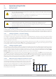

Table Of Contents
- 1. General
- 1.1 About this document
- 1.2 Warranty
- 1.3 Limitation of liability
- 1.4 Disposal of equipment
- 1.5 Product key
- 1.6 Intended usage
- 1.7 Safety
- 1.8 Technical Data
- 1.9 Construction and function
- 1.9.1 General description
- 1.9.2 Block diagram
- 1.9.3 Scope of delivery
- 1.9.4 Accessories
- 1.9.5 Options
- 1.9.6 The control panel (HMI)
- 1.9.7 USB port (rear side)
- 1.9.8 Interface module slot
- 1.9.9 Analog interface
- 1.9.10 “Share BUS” connector
- 1.9.11 “Sense” connector (remote sensing)
- 1.9.12 Master-Slave bus
- 1.9.13 Ethernet port
- 2. Installation & commissioning
- 2.1 Transport and storage
- 2.2 Unpacking and visual check
- 2.3 Installation
- 2.3.1 Safety procedures before installation and use
- 2.3.2 Preparation
- 2.3.3 Installing the device
- 2.3.4 Connection to AC supply
- 2.3.5 Connection to DC sources
- 2.3.6 Connection of remote sensing
- 2.3.7 Grounding of the DC terminal
- 2.3.8 Installation of an interface module
- 2.3.9 Connection of the analog interface
- 2.3.10 Connection of the Share bus
- 2.3.11 Connection of the USB port (rear side)
- 2.3.12 Initial commission
- 2.3.13 Commission after a firmware update or a long period of non-use
- 3. Operation and application
- 3.1 Important notes
- 3.2 Operating modes
- 3.3 Alarm conditions
- 3.4 Manual operation
- 3.5 Remote control
- 3.6 Alarms and monitoring
- 3.7 Locking the control panel (HMI)
- 3.8 Locking the adjustment limits and user profiles
- 3.9 Loading and saving user profiles
- 3.10 The function generator
- 3.10.1 Introduction
- 3.10.2 General
- 3.10.3 Method of operation
- 3.10.4 Manual operation
- 3.10.5 Sine wave function
- 3.10.6 Triangular function
- 3.10.7 Rectangular function
- 3.10.8 Trapezoidal function
- 3.10.9 DIN 40839 function
- 3.10.10 Arbitrary function
- 3.10.11 Ramp function
- 3.10.12 IU table function (XY table)
- 3.10.13 Battery test function
- 3.10.14 MPP tracking function
- 3.10.15 Remote control of the function generator
- 3.11 Other applications
- 4. Service and maintenance
- 5. Contact and support

© EA Elektro-Automatik in 2022, this information is subject to change without notice 3733200840_manual_elr_10000_2u_3kw_en_02
3.2.2 Current regulation / constant current / current limiting
Current regulation is also known as current limiting or constant current mode (CC).
The current in the DC input of the device is held constant once the current consumed by the load reaches the adjusted limit.
Then the device automatically switches to CC. As long as the input current is lower than the adjusted current limit, the device
will be either in constant voltage or constant power mode. If, however, the power consumption reaches the set maximum
power value, the device will switch automatically to power limiting and set voltage and current according to P = U * I.
While the DC power stage is switched on and constant current mode is active, the condition “CC mode active” will be indicated
on the graphics display by the abbreviation CC and this message will be passed as a signal to the analog interface, as well
stored as status which can also be read as via digital interface.
3.2.3 Power regulation / constant power / power limiting
Power regulation, also known as power limiting or constant power (CP), keeps the DC
power constant if the DC input current in relation to the DC input voltage reaches the
adjusted limit according to P = U * I.
Power limiting operates according to the auto-range principle such that at lower voltages
higher current can ow and vice versa, always in order to maintain constant power within
the range PN (see diagram to the right).
While the DC power stage is switched on and constant power mode is active, the condi-
tion “CP mode active” will be indicated on the graphics display by the abbreviation CP, as
well stored as status which can also be read as a status message via digital interface.
Figure 14 - Power range
3.2.3.1 Power derating
All models in this series can operate worldwide on common grid voltages such as 120 V or 230 V. In order to limit the AC current
when running on low input voltages, they switch to a derating mode which reduces the available DC power. The switchover
is determined once when the device is powered and depends on the currently present AC supply voltage. It means that it
cannot switch back and forth between derated and not derated mode during operation. The model specic derated power is
dened as 1200 W (adjustment range: 0...1224 W) for 1500 W models and as 1500 W (adjustment range: 0...1530 W) for 3000
W models. Also see
“1.8.3. Specic technical data”
. The full power a model is rated for is thus only available with AC voltages
from 208 V or higher. Once derated, the device would show a permanent information in the display and all values related to
the power are reduced in their adjustment range. This also applies to master-slave operation of derated units.
3.2.4 Resistance regulation / constant resistance
Inside electronic loads, whose operating principle is based on a variable internal resistance, constant resistance mode (CR) is
almost a natural characteristic. The load attempts to set the internal resistance to the user dened value by determining the
input current depending on the input voltage according to Ohm’s law I
IN
= U
IN
/ R
SET
. The internal resistance is naturally limited
between almost zero and maximum (resolution of current regulation too inaccurate). As the internal resistance cannot have
a value of zero, the lower limit is dened to an achievable minimum. This ensures that the electronic load, at very low input
voltages, can consume a high input current from the source, up to the maximum.
While the DC input is switched on and con-
stant resistance mode is active, the condition “CR mode active” will be indicated on the graphics display by the abbreviation
CR, as well it will be stored as internal status which can be read via digital interface.
3.2.5 Dynamic characteristics and stability criteria
The device is an electronic load which is characterized by short rise and fall times of the current, achieved by a high bandwidth
of the internal regulation circuit.
In case of testing sources with own regulation circuits, like for example power supplies, a regulation instability may occur.
This instability is caused if the complete system (feeding source and electronic load) has too little phase and gain margin at
certain frequencies. 180 ° phase shift at > 0dB amplication fullls the condition for an oscillation and results in instability.
The same can occur when using sources without own regulation circuit like batteries and when the connection cables are
highly inductive or inductive-capacitive.
The instability is not caused by a malfunction of the load, but by the behavior of the complete system. An improvement of
the phase and gain margin can solve this. In practice, this is primarily done by switching the internal voltage regulator be-
tween dynamics modes called Slow, Fast and Normal. The switch is either found in the device settings (see
3.4.3.1
) or the
quick menu (see
3.4.9
). The user can only try the different settings to see if the desired effect is achieved. Should there be
an improvement due to one of these settings, but the oscillation remains, an additional measure can be to install a capacity
directly to the DC input, perhaps alternatively to the remote sense input, if connected to the source. The value to achieve the
expected result is not dened and has to be found out. We recommend:
Models 80 V: 1000uF....4700uF
Models 200/360 V: 100uF...470uF
Models 500 V: 47uF...150uF
Models 750/1000 V: 22uF...100uF
Models 1500 V: 4.7uF...22uF