
Manual
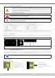
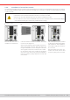
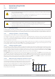

Table Of Contents
- 1. General
- 1.1 About this document
- 1.2 Warranty
- 1.3 Limitation of liability
- 1.4 Disposal of equipment
- 1.5 Product key
- 1.6 Intended usage
- 1.7 Safety
- 1.8 Technical Data
- 1.9 Construction and function
- 1.9.1 General description
- 1.9.2 Block diagram
- 1.9.3 Scope of delivery
- 1.9.4 Accessories
- 1.9.5 Options
- 1.9.6 The control panel (HMI)
- 1.9.7 USB port (rear side)
- 1.9.8 Interface module slot
- 1.9.9 Analog interface
- 1.9.10 “Share BUS” connector
- 1.9.11 “Sense” connector (remote sensing)
- 1.9.12 Master-Slave bus
- 1.9.13 Ethernet port
- 2. Installation & commissioning
- 2.1 Transport and storage
- 2.2 Unpacking and visual check
- 2.3 Installation
- 2.3.1 Safety procedures before installation and use
- 2.3.2 Preparation
- 2.3.3 Installing the device
- 2.3.4 Connection to AC supply
- 2.3.5 Connection to DC sources
- 2.3.6 Connection of remote sensing
- 2.3.7 Grounding of the DC terminal
- 2.3.8 Installation of an interface module
- 2.3.9 Connection of the analog interface
- 2.3.10 Connection of the Share bus
- 2.3.11 Connection of the USB port (rear side)
- 2.3.12 Initial commission
- 2.3.13 Commission after a firmware update or a long period of non-use
- 3. Operation and application
- 3.1 Important notes
- 3.2 Operating modes
- 3.3 Alarm conditions
- 3.4 Manual operation
- 3.5 Remote control
- 3.6 Alarms and monitoring
- 3.7 Locking the control panel (HMI)
- 3.8 Locking the adjustment limits and user profiles
- 3.9 Loading and saving user profiles
- 3.10 The function generator
- 3.10.1 Introduction
- 3.10.2 General
- 3.10.3 Method of operation
- 3.10.4 Manual operation
- 3.10.5 Sine wave function
- 3.10.6 Triangular function
- 3.10.7 Rectangular function
- 3.10.8 Trapezoidal function
- 3.10.9 DIN 40839 function
- 3.10.10 Arbitrary function
- 3.10.11 Ramp function
- 3.10.12 IU table function (XY table)
- 3.10.13 Battery test function
- 3.10.14 MPP tracking function
- 3.10.15 Remote control of the function generator
- 3.11 Other applications
- 4. Service and maintenance
- 5. Contact and support

© EA Elektro-Automatik in 2022, this information is subject to change without notice 3633200840_manual_elr_10000_2u_3kw_en_02
3. Operation and application
3.1 Important notes
3.1.1 Personal safety
• In order to guarantee safety when using the device, it’s essential that only persons operate the device
who are fully acquainted and trained in the required safety measures to be taken when working with
dangerous electrical voltages
• For models which can generate a voltage which is dangerous by contact, or is connected to such, the
included DC terminal cover, or an equivalent, must always be used
• Read and follow all safety warnings in section
1.7.1
!
3.1.2 General
• When running the device in source mode, unloaded operation is not considered as a normal operation
mode and can thus lead to false measurements, for example when calibrating the device
• The optimal working point of the device is between 50% and 100% voltage and current
• It’s recommended to not run the device below 10% voltage and current, in order to make sure technical
values like ripple and transient times can be met
3.2 Operating modes
A power supply is internally controlled by different control or regulation circuits, which shall bring voltage, current and power
to the adjusted values and hold them constant, if possible. These circuits follow typical laws of control systems engineering,
resulting in different operating modes. Every operating mode has its own characteristics which is explained below in short form.
3. 2 .1 Voltage regulation / Constant voltage
Voltage regulation is also called constant voltage operation (CV).
The voltage on the DC input of the device is held constant on the adjusted value, unless the current or the power according
to P = UDC * I reaches the adjusted current or power limit. In both cases the device will automatically change to constant
current or constant power operation, whatever occurs rst. Then the voltage can’t be held constant anymore and will rise to
a value resulting from Ohm’s law.
While the DC power stage is switched on and constant voltage mode is active, the condition “CV mode active” will be indicated
on the graphics display by the abbreviation CV and this message will be passed as a signal to the analog interface, as well
stored as status which can also be read as a status message via digital interface.
3. 2 .1.1 Voltage regulation peaks
When working in constant voltage regulation (CV) and when the device has to react to a voltage change on the DC input, which
is usually caused by the external source, the load requires a small transient time to settle the voltage. Positive voltage steps,
i.e. lower to higher voltage, will cause the voltage to overshoot for a short time until compensated by the voltage regulator.
The time it takes to settle the voltage can be inuenced by switching the voltage regulation speed between the settings Slow,
Normal and Fast, whereas Normal is the default. Also see
“3.4.3.1. Sub menu “Settings””
.
Setting Slow will result in a higher transient time and higher deviation from the set value, while Fast is vice versa and shortens
the peaks. As a side effect and with the regulator being set to Fast, the load would react quicker to HF couplings and have a
higher oscillation tendency, especially when using remote sensing. The choice of this setting thus depends on the situation.
When using remote sensing, a typical recommendation would be to set Slow or, in case Fast is required for certain reasons,
to disconnect the remote sensing terminals temporarily or permanently.
3.2.1.2 Minimum input voltage for maximum current
Due to technical reasons, all models in this series have a minimum inter-
nal resistance that requires to provide a specic minimum input voltage
(U
MIN
) in order for the device to be able to sink its rated current (I
MAX
).
This minimum input voltage varies from model to model and can easily
be determined. If less voltage than U
MIN
is supplied, the load proportion-
ally draws less current, which can be calculated easily.
See principle view to the right.
I(A)
U(V)
I
Umin
Imax