
Manual
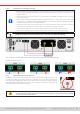
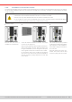
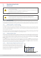

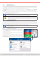
Table Of Contents
- 1. General
- 1.1 About this document
- 1.2 Warranty
- 1.3 Limitation of liability
- 1.4 Disposal of equipment
- 1.5 Product key
- 1.6 Intended usage
- 1.7 Safety
- 1.8 Technical Data
- 1.9 Construction and function
- 1.9.1 General description
- 1.9.2 Block diagram
- 1.9.3 Scope of delivery
- 1.9.4 Accessories
- 1.9.5 Options
- 1.9.6 The control panel (HMI)
- 1.9.7 USB port (rear side)
- 1.9.8 Interface module slot
- 1.9.9 Analog interface
- 1.9.10 “Share BUS” connector
- 1.9.11 “Sense” connector (remote sensing)
- 1.9.12 Master-Slave bus
- 1.9.13 Ethernet port
- 2. Installation & commissioning
- 2.1 Transport and storage
- 2.2 Unpacking and visual check
- 2.3 Installation
- 2.3.1 Safety procedures before installation and use
- 2.3.2 Preparation
- 2.3.3 Installing the device
- 2.3.4 Connection to AC supply
- 2.3.5 Connection to DC sources
- 2.3.6 Connection of remote sensing
- 2.3.7 Grounding of the DC terminal
- 2.3.8 Installation of an interface module
- 2.3.9 Connection of the analog interface
- 2.3.10 Connection of the Share bus
- 2.3.11 Connection of the USB port (rear side)
- 2.3.12 Initial commission
- 2.3.13 Commission after a firmware update or a long period of non-use
- 3. Operation and application
- 3.1 Important notes
- 3.2 Operating modes
- 3.3 Alarm conditions
- 3.4 Manual operation
- 3.5 Remote control
- 3.6 Alarms and monitoring
- 3.7 Locking the control panel (HMI)
- 3.8 Locking the adjustment limits and user profiles
- 3.9 Loading and saving user profiles
- 3.10 The function generator
- 3.10.1 Introduction
- 3.10.2 General
- 3.10.3 Method of operation
- 3.10.4 Manual operation
- 3.10.5 Sine wave function
- 3.10.6 Triangular function
- 3.10.7 Rectangular function
- 3.10.8 Trapezoidal function
- 3.10.9 DIN 40839 function
- 3.10.10 Arbitrary function
- 3.10.11 Ramp function
- 3.10.12 IU table function (XY table)
- 3.10.13 Battery test function
- 3.10.14 MPP tracking function
- 3.10.15 Remote control of the function generator
- 3.11 Other applications
- 4. Service and maintenance
- 5. Contact and support

© EA Elektro-Automatik in 2022, this information is subject to change without notice 3533200840_manual_elr_10000_2u_3kw_en_02
2.3.9 Connection of the analog interface
The 15 pole connector (type: D-sub, VGA) on the rear side is an analog interface. To connect this to a controlling hardware
(PC, electronic circuit), a standard plug is necessary (not included in the scope of delivery). It’s generally advisable to switch
the device completely off before connecting or disconnecting this connector, but at least the DC terminal.
2.3.10 Connection of the Share bus
The “Share BUS” connectors on the rear side (2x BNC type) can be used to connect to the Share bus of further units. The
main purpose of the Share bus is to balance the voltage of multiple units in parallel operation, especially when using the inte-
grated function generator of the master unit. For further information about parallel operation refer to section
“3.11.1. Parallel
operation in master-slave (MS)”
.
2.3.11 Connection of the USB port (rear side)
In order to remotely control the device via this port, connect the device with a PC using the included USB cable and switch
the device on.
2 . 3 .11.1 Driver installation (Windows)
On the initial connection with a PC the operating system will identify the device as new hardware and will try to install a driver.
The required driver is for a Communications Device Class (CDC) device and is usually integrated in current operating systems
such as Windows 7 or 10. But it’s strongly recommended to use and install the included driver installer (on USB stick) to gain
maximum compatibility of the device to our softwares.
2.3.11.2 Driver installation (Linux, MacOS)
We can’t provide drivers or installation instructions for these operating systems. Whether a suitable driver is available is best
carried out by searching the Internet.
2.3.11.3 Alternative drivers
In case the CDC drivers described above are not available on your system, or for some reason do not function correctly, com-
mercial suppliers can help. Search the Internet for suppliers using the keywords “cdc driver windows“ or “cdc driver linux“ or
“cdc driver macos“.
2.3.12 Initial commission
For the rst start-up after installation of the device, the following procedures have to be executed:
• Conrm that the connection cables to be used are of a satisfactory cross section!
• Check if the factory settings of set values, safety and monitoring functions and communication are suitable for your intended
application of the device and adjust them if required, as described in the manual!
• In case of remote control via PC, read the additional documentation for interfaces and software!
• In case of remote control via the analog interface, read the section in this manual concerning analog interfaces!
2.3.13 Commission after a rmware update or a long period of non-use
In case of a rmware update, return of the equipment following repair or a location or conguration change, similar measures
should be taken to those of initial start up. Refer to
“2.3.12. Initial commission”
.
Only after successful checking of the device as listed may it be operated as usual.