
Manual
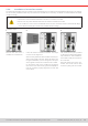
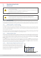
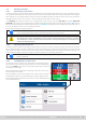
Table Of Contents
- 1. General
- 1.1 About this document
- 1.2 Warranty
- 1.3 Limitation of liability
- 1.4 Disposal of equipment
- 1.5 Product key
- 1.6 Intended usage
- 1.7 Safety
- 1.8 Technical Data
- 1.9 Construction and function
- 1.9.1 General description
- 1.9.2 Block diagram
- 1.9.3 Scope of delivery
- 1.9.4 Accessories
- 1.9.5 Options
- 1.9.6 The control panel (HMI)
- 1.9.7 USB port (rear side)
- 1.9.8 Interface module slot
- 1.9.9 Analog interface
- 1.9.10 “Share BUS” connector
- 1.9.11 “Sense” connector (remote sensing)
- 1.9.12 Master-Slave bus
- 1.9.13 Ethernet port
- 2. Installation & commissioning
- 2.1 Transport and storage
- 2.2 Unpacking and visual check
- 2.3 Installation
- 2.3.1 Safety procedures before installation and use
- 2.3.2 Preparation
- 2.3.3 Installing the device
- 2.3.4 Connection to AC supply
- 2.3.5 Connection to DC sources
- 2.3.6 Connection of remote sensing
- 2.3.7 Grounding of the DC terminal
- 2.3.8 Installation of an interface module
- 2.3.9 Connection of the analog interface
- 2.3.10 Connection of the Share bus
- 2.3.11 Connection of the USB port (rear side)
- 2.3.12 Initial commission
- 2.3.13 Commission after a firmware update or a long period of non-use
- 3. Operation and application
- 3.1 Important notes
- 3.2 Operating modes
- 3.3 Alarm conditions
- 3.4 Manual operation
- 3.5 Remote control
- 3.6 Alarms and monitoring
- 3.7 Locking the control panel (HMI)
- 3.8 Locking the adjustment limits and user profiles
- 3.9 Loading and saving user profiles
- 3.10 The function generator
- 3.10.1 Introduction
- 3.10.2 General
- 3.10.3 Method of operation
- 3.10.4 Manual operation
- 3.10.5 Sine wave function
- 3.10.6 Triangular function
- 3.10.7 Rectangular function
- 3.10.8 Trapezoidal function
- 3.10.9 DIN 40839 function
- 3.10.10 Arbitrary function
- 3.10.11 Ramp function
- 3.10.12 IU table function (XY table)
- 3.10.13 Battery test function
- 3.10.14 MPP tracking function
- 3.10.15 Remote control of the function generator
- 3.11 Other applications
- 4. Service and maintenance
- 5. Contact and support

© EA Elektro-Automatik in 2022, this information is subject to change without notice 3433200840_manual_elr_10000_2u_3kw_en_02
2.3.8 Installation of an interface module
The optionally obtainable interface modules can be retrotted by the user and are exchangeable with each other. The settings
for the currently installed module vary and need to be checked and, if necessary, corrected on initial installation and after
module exchange.
• Common ESD protection procedures apply when inserting or exchanging a module.
• The device must be switched off before insertion or removal of a module
• Never insert any other hardware other than an interface module into the slot
• If no module is in use it’s recommended that the slot cover is mounted in order to avoid internal dirtying
of the device and changes in the air ow (models with air-cooling)
Installation steps:
1. 2. 3.
Remove the slot cover. If
needed, use a screw driver.
Insert the interface module into the slot. The shape
ensures correct alignment.
When inserting take care that it’s held as close as pos-
sible to a 90° angle to the rear wall of the device. Use
the green PCB which you can recognize on the open
slot as guide. At the end is a socket for the module.
On the bottom side of the module are two plastic
nibs which must click into the green board (PCB) so
that the module is properly aligned on the rear wall
of the device.
The screws (Torx 8) are provided
for xing the module and should be
fully screwed in. After installation,
the module is ready for use and can
be connected.
Removal follows the reverse pro-
cedure. The screws can be used
to assist in pulling out the module.