
Manual
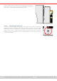
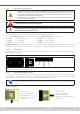
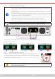
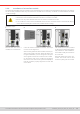
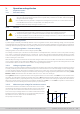

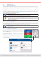
Table Of Contents
- 1. General
- 1.1 About this document
- 1.2 Warranty
- 1.3 Limitation of liability
- 1.4 Disposal of equipment
- 1.5 Product key
- 1.6 Intended usage
- 1.7 Safety
- 1.8 Technical Data
- 1.9 Construction and function
- 1.9.1 General description
- 1.9.2 Block diagram
- 1.9.3 Scope of delivery
- 1.9.4 Accessories
- 1.9.5 Options
- 1.9.6 The control panel (HMI)
- 1.9.7 USB port (rear side)
- 1.9.8 Interface module slot
- 1.9.9 Analog interface
- 1.9.10 “Share BUS” connector
- 1.9.11 “Sense” connector (remote sensing)
- 1.9.12 Master-Slave bus
- 1.9.13 Ethernet port
- 2. Installation & commissioning
- 2.1 Transport and storage
- 2.2 Unpacking and visual check
- 2.3 Installation
- 2.3.1 Safety procedures before installation and use
- 2.3.2 Preparation
- 2.3.3 Installing the device
- 2.3.4 Connection to AC supply
- 2.3.5 Connection to DC sources
- 2.3.6 Connection of remote sensing
- 2.3.7 Grounding of the DC terminal
- 2.3.8 Installation of an interface module
- 2.3.9 Connection of the analog interface
- 2.3.10 Connection of the Share bus
- 2.3.11 Connection of the USB port (rear side)
- 2.3.12 Initial commission
- 2.3.13 Commission after a firmware update or a long period of non-use
- 3. Operation and application
- 3.1 Important notes
- 3.2 Operating modes
- 3.3 Alarm conditions
- 3.4 Manual operation
- 3.5 Remote control
- 3.6 Alarms and monitoring
- 3.7 Locking the control panel (HMI)
- 3.8 Locking the adjustment limits and user profiles
- 3.9 Loading and saving user profiles
- 3.10 The function generator
- 3.10.1 Introduction
- 3.10.2 General
- 3.10.3 Method of operation
- 3.10.4 Manual operation
- 3.10.5 Sine wave function
- 3.10.6 Triangular function
- 3.10.7 Rectangular function
- 3.10.8 Trapezoidal function
- 3.10.9 DIN 40839 function
- 3.10.10 Arbitrary function
- 3.10.11 Ramp function
- 3.10.12 IU table function (XY table)
- 3.10.13 Battery test function
- 3.10.14 MPP tracking function
- 3.10.15 Remote control of the function generator
- 3.11 Other applications
- 4. Service and maintenance
- 5. Contact and support

© EA Elektro-Automatik in 2022, this information is subject to change without notice 3333200840_manual_elr_10000_2u_3kw_en_02
2.3.6 Connection of remote sensing
•
Remote sensing is only effective during constant voltage operation (CV) and for other regulation modes
the sense input should be disconnected, if possible, because connecting it generally increases the os-
cillation tendency
•
The cross section of the sense cables is noncritical. Recommendation for cables up to 5 m (16.4 ft):
use at least 0.5 mm²
•
Sense cables shouldn’t be twisted, but laid close to the DC cables, i. e. Sense- cable close to DC- cable
to the source etc. to damp or avoid possible oscillation. If necessary, an additional capacitor should be
installed at the load/source to eliminate oscillation
•
The Sense+ cable must be connected to DC+ on the source and Sense- to DC- at the source, otherwise
the sense input of the device can be damaged. For an example see Figure 13 below.
•
In master-slave operation, the remote sensing should be connected to the master unit only
•
The dielectric strength of the sense wires must always at least match the DC voltage rating!
Dangerous voltage on the sense terminals! The sense cover must always be installed.
Figure 13 - Example for remote sensing wiring (DC terminal and Sense terminal covers left way for illustrative purposes)
Allowed connection schemes:
2.3.7 Grounding of the DC terminal
Besides the main purpose of grounding the enclosure, the extra grounding point (item “10” in
1.8.4.3
) can be used to ground any the DC terminal poles. Doing so causes a potential shift
on the opposite pole against PE. Because of insulation, there is a maximum allowed potential
shift dened for the negative DC terminal pole, which depends on the device model. Refer to
“1.8.3. Specic technical data”
for the levels.
In case any DC pole is grounded, the operator of the device must reinstate the basic protection for
human safety by installing appropriate external means, for instance a cover, everywhere the potential
of the DC terminal is connected to.