
Manual
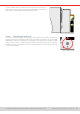
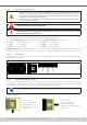
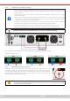
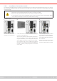
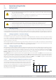
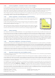
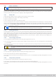

Table Of Contents
- 1. General
- 1.1 About this document
- 1.2 Warranty
- 1.3 Limitation of liability
- 1.4 Disposal of equipment
- 1.5 Product key
- 1.6 Intended usage
- 1.7 Safety
- 1.8 Technical Data
- 1.9 Construction and function
- 1.9.1 General description
- 1.9.2 Block diagram
- 1.9.3 Scope of delivery
- 1.9.4 Accessories
- 1.9.5 Options
- 1.9.6 The control panel (HMI)
- 1.9.7 USB port (rear side)
- 1.9.8 Interface module slot
- 1.9.9 Analog interface
- 1.9.10 “Share BUS” connector
- 1.9.11 “Sense” connector (remote sensing)
- 1.9.12 Master-Slave bus
- 1.9.13 Ethernet port
- 2. Installation & commissioning
- 2.1 Transport and storage
- 2.2 Unpacking and visual check
- 2.3 Installation
- 2.3.1 Safety procedures before installation and use
- 2.3.2 Preparation
- 2.3.3 Installing the device
- 2.3.4 Connection to AC supply
- 2.3.5 Connection to DC sources
- 2.3.6 Connection of remote sensing
- 2.3.7 Grounding of the DC terminal
- 2.3.8 Installation of an interface module
- 2.3.9 Connection of the analog interface
- 2.3.10 Connection of the Share bus
- 2.3.11 Connection of the USB port (rear side)
- 2.3.12 Initial commission
- 2.3.13 Commission after a firmware update or a long period of non-use
- 3. Operation and application
- 3.1 Important notes
- 3.2 Operating modes
- 3.3 Alarm conditions
- 3.4 Manual operation
- 3.5 Remote control
- 3.6 Alarms and monitoring
- 3.7 Locking the control panel (HMI)
- 3.8 Locking the adjustment limits and user profiles
- 3.9 Loading and saving user profiles
- 3.10 The function generator
- 3.10.1 Introduction
- 3.10.2 General
- 3.10.3 Method of operation
- 3.10.4 Manual operation
- 3.10.5 Sine wave function
- 3.10.6 Triangular function
- 3.10.7 Rectangular function
- 3.10.8 Trapezoidal function
- 3.10.9 DIN 40839 function
- 3.10.10 Arbitrary function
- 3.10.11 Ramp function
- 3.10.12 IU table function (XY table)
- 3.10.13 Battery test function
- 3.10.14 MPP tracking function
- 3.10.15 Remote control of the function generator
- 3.11 Other applications
- 4. Service and maintenance
- 5. Contact and support

© EA Elektro-Automatik in 2022, this information is subject to change without notice 3233200840_manual_elr_10000_2u_3kw_en_02
2.3.5 Connection to DC sources
• In the case of a device with a high nominal DC current and hence a thick and heavy DC connection
cable it’s necessary to take account of the weight of the cable and the strain imposed on the DC
connection. Especially when mounted in a 19” cabinet or similar, where the cable could hang on the
DC terminal, a strain reliever should be used.
• Besides the proper cross section of DC cables the proper electric strength (withstand voltage) of
the cables must be considered.
No false polarity protection inside! When connecting sources with false polarity the device will be
damaged, also when the device isn’t powered!
When connected to DC, an external source charges the internal capacities on the DC terminal, even
when the device isn’t powered. Dangerous voltage levels can be present on the DC terminal, even after
disconnection of that external source.
The DC terminal is located on the rear side of the device and is not protected by a fuse. The cross section of the connection
cable is determined by the current consumption, cable length and ambient temperature.
For cables up to 5 m (16.4 ft) and average ambient temperature up to 30°C (86 °F), we recommend:
up to 10 A: 0.75 mm² (AWG18) up to 20 A: 2.5 mm² (AWG13)
up to 30 A: 4 mm² (AWG10) up to 50 A: 10 mm² (AWG8)
up to 60 A: 16 mm² (AWG6) up to 120 A: 35 mm² (AWG2)
per connection pole (multi-conductor, insulated, openly suspended). Single cables of, for example, 70 mm² may be replaced
by e.g. 2x 35 mm² etc. If the cables are long then the cross section must be increased to avoid voltage loss and overheating.
2.3.5.1 DC terminal
The table below shows an overview of the DC terminal. It’s recommended that connection of load cables always utilizes
exible cables with ring lugs.
All models
M6 bolt on a metal rail
Recommendation: ring lug with a 6.5 mm hole
2.3.5.2 Cable lead and plastic cover
For the DC terminal there are two plastic covers for contact protection included. The bigger one can be installed alternatively
to the smaller one or at the same time, because it covers the small one. However, one of them must always be installed. There
are breakouts in the bigger cover so that the supply cable can be laid in various directions.
The connection angle and the required bending radius for the DC cable must be taken into account when
planning the depth of the complete device, especially when installing in a 19” cabinet or similar installa-
tions.
Installation examples:
• 90° up or down
• Space saving in depth
• No bending radius
• Only possible with the
bigger cover
• Horizontal lead
• Space saving in height
• Large bending radius
• Possible with the smaller or the
bigger cover