
Manual
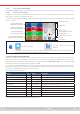
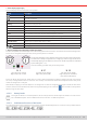
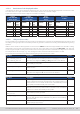
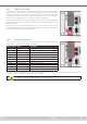
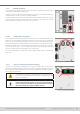
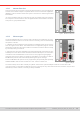
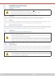
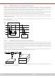
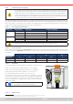
Table Of Contents
- 1. General
- 1.1 About this document
- 1.2 Warranty
- 1.3 Limitation of liability
- 1.4 Disposal of equipment
- 1.5 Product key
- 1.6 Intended usage
- 1.7 Safety
- 1.8 Technical Data
- 1.9 Construction and function
- 1.9.1 General description
- 1.9.2 Block diagram
- 1.9.3 Scope of delivery
- 1.9.4 Accessories
- 1.9.5 Options
- 1.9.6 The control panel (HMI)
- 1.9.7 USB port (rear side)
- 1.9.8 Interface module slot
- 1.9.9 Analog interface
- 1.9.10 “Share BUS” connector
- 1.9.11 “Sense” connector (remote sensing)
- 1.9.12 Master-Slave bus
- 1.9.13 Ethernet port
- 2. Installation & commissioning
- 2.1 Transport and storage
- 2.2 Unpacking and visual check
- 2.3 Installation
- 2.3.1 Safety procedures before installation and use
- 2.3.2 Preparation
- 2.3.3 Installing the device
- 2.3.4 Connection to AC supply
- 2.3.5 Connection to DC sources
- 2.3.6 Connection of remote sensing
- 2.3.7 Grounding of the DC terminal
- 2.3.8 Installation of an interface module
- 2.3.9 Connection of the analog interface
- 2.3.10 Connection of the Share bus
- 2.3.11 Connection of the USB port (rear side)
- 2.3.12 Initial commission
- 2.3.13 Commission after a firmware update or a long period of non-use
- 3. Operation and application
- 3.1 Important notes
- 3.2 Operating modes
- 3.3 Alarm conditions
- 3.4 Manual operation
- 3.5 Remote control
- 3.6 Alarms and monitoring
- 3.7 Locking the control panel (HMI)
- 3.8 Locking the adjustment limits and user profiles
- 3.9 Loading and saving user profiles
- 3.10 The function generator
- 3.10.1 Introduction
- 3.10.2 General
- 3.10.3 Method of operation
- 3.10.4 Manual operation
- 3.10.5 Sine wave function
- 3.10.6 Triangular function
- 3.10.7 Rectangular function
- 3.10.8 Trapezoidal function
- 3.10.9 DIN 40839 function
- 3.10.10 Arbitrary function
- 3.10.11 Ramp function
- 3.10.12 IU table function (XY table)
- 3.10.13 Battery test function
- 3.10.14 MPP tracking function
- 3.10.15 Remote control of the function generator
- 3.11 Other applications
- 4. Service and maintenance
- 5. Contact and support

© EA Elektro-Automatik in 2022, this information is subject to change without notice 3033200840_manual_elr_10000_2u_3kw_en_02
2.3.4 Connection to AC supply
• Connection to an AC supply must only be carried out by qualied personnel and the device must always
be run directly on a power grid (transformer are permitted) and not on generators or UPS equipment!
• Cable cross section must be suitable for the maximum input current of the device! See tables below. The
device should furthermore be fused externally and according to the current rating and cable cross section
• Ensure that all regulations for the operation of the device and connection to the public grid of energy
recovering equipment have been considered and requirements have been met!
All models and variants in this series support to run either on 220/230/240 V or also 110/120 V (USA grid). When running on
110/120 V all models automatically switch into derated power mode in which the available DC power is decreased to 1.5kW
with 3 kW models or 1.2 kW with 1.5 kW models. This is detected every time when powering the device, so that the same
model could provide the rated power when being run on 220/230/240V.
2.3.4.1 AC supply requirements
Rated power Supply voltage Supply type DC power in derating
1500 W
110 / 120 V Single phase (L, N, PE) 1200 W
208 V Two-phase (2x L, PE) -
230 / 240 V Single phase (L, N, PE) -
3000 W
110 / 120 V Single phase (L, N, PE) 1500 W
208 V Two-phase (2x L, PE) -
230 / 240 V Single phase (L, N, PE) -
The PE conductor is imperative and must always be wired to the 3 pole AC terminal!
2.3.4.2 Cross section
For the selection of a suitable cable cross section the rated AC current of the device and the cable length are decisive. Based
on the connection of a single unit the table lists the maximum input current and recommended minimum cross section for
each phase:
L N PE
(1
Rated power ø I
Max
(2
ø I
Max
(2
ø
1500 W ≥1 mm² (AWG18) 14.4 A ≥1 mm² (AWG18) 14.4 A ≥1 mm² (AWG18)
3000 W ≥1.5 mm² (AWG16) 17.8 A ≥1.5 mm² (AWG16) 17.8 A ≥1.5 mm² (AWG16)
2.3.4.3 AC cable
It’s recommended to use cable end sleeves. Denition of the AC terminal:
• Max. cross section without cable end sleeve: 10 mm² (AWG8)
• Max. wire cross section with cable end sleeve: 6 mm² (AWG10)
• Stripping length without cable end sleeve: 11-13 mm (0.5 in)
• Length of cable end sleeve, if used: min. 10 mm (0.4 in)
The included connection plug can receive loose, soldered or crimped
cable ends. The longer the connection cable, the higher the voltage loss
due to the cable resistance. Therefore the mains cables should be kept
as short as possible or use bigger cross section. See the connection
scheme to the right.
The AC cable, as symbolically depicted in the right-
hand gure, is not included in the delivery.
Figure 10 - AC cable configuration example
2.3.4.4 Strain relief
1 Valid for both, the ground conductor in the AC cable and the separate PE line for enclosure grounding
2 At the lowest possible AC supply voltage on the AC input and full output power