
Manual


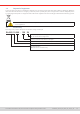

Table Of Contents
- 1. General
- 1.1 About this document
- 1.2 Warranty
- 1.3 Limitation of liability
- 1.4 Disposal of equipment
- 1.5 Product key
- 1.6 Intended usage
- 1.7 Safety
- 1.8 Technical Data
- 1.9 Construction and function
- 1.9.1 General description
- 1.9.2 Block diagram
- 1.9.3 Scope of delivery
- 1.9.4 Accessories
- 1.9.5 Options
- 1.9.6 The control panel (HMI)
- 1.9.7 USB port (rear side)
- 1.9.8 Interface module slot
- 1.9.9 Analog interface
- 1.9.10 “Share BUS” connector
- 1.9.11 “Sense” connector (remote sensing)
- 1.9.12 Master-Slave bus
- 1.9.13 Ethernet port
- 2. Installation & commissioning
- 2.1 Transport and storage
- 2.2 Unpacking and visual check
- 2.3 Installation
- 2.3.1 Safety procedures before installation and use
- 2.3.2 Preparation
- 2.3.3 Installing the device
- 2.3.4 Connection to AC supply
- 2.3.5 Connection to DC sources
- 2.3.6 Connection of remote sensing
- 2.3.7 Grounding of the DC terminal
- 2.3.8 Installation of an interface module
- 2.3.9 Connection of the analog interface
- 2.3.10 Connection of the Share bus
- 2.3.11 Connection of the USB port (rear side)
- 2.3.12 Initial commission
- 2.3.13 Commission after a firmware update or a long period of non-use
- 3. Operation and application
- 3.1 Important notes
- 3.2 Operating modes
- 3.3 Alarm conditions
- 3.4 Manual operation
- 3.5 Remote control
- 3.6 Alarms and monitoring
- 3.7 Locking the control panel (HMI)
- 3.8 Locking the adjustment limits and user profiles
- 3.9 Loading and saving user profiles
- 3.10 The function generator
- 3.10.1 Introduction
- 3.10.2 General
- 3.10.3 Method of operation
- 3.10.4 Manual operation
- 3.10.5 Sine wave function
- 3.10.6 Triangular function
- 3.10.7 Rectangular function
- 3.10.8 Trapezoidal function
- 3.10.9 DIN 40839 function
- 3.10.10 Arbitrary function
- 3.10.11 Ramp function
- 3.10.12 IU table function (XY table)
- 3.10.13 Battery test function
- 3.10.14 MPP tracking function
- 3.10.15 Remote control of the function generator
- 3.11 Other applications
- 4. Service and maintenance
- 5. Contact and support

© EA Elektro-Automatik in 2022, this information is subject to change without notice 333200840_manual_elr_10000_2u_3kw_en_02
3.5.3 Remote control via a digital interface 54
3.5.4 Remote control via the analog interface 56
3.6 Alarms and monitoring 60
3.6.1 Definition of terms 60
3.6.2 Device alarm and event handling 60
3.7 Locking the control panel (HMI) 63
3.8 Locking the adjustment limits and user pro-
files 63
3.9 Loading and saving user profiles 64
3.10 The function generator 65
3.10.1 Introduction 65
3.10.2 General 65
3.10.3 Method of operation 66
3.10.4 Manual operation 66
3.10.5 Sine wave function 67
3.10.6 Triangular function 68
3.10.7 Rectangular function 68
3.10.8 Trapezoidal function 69
3.10.9 DIN 40839 function 69
3.10.10 Arbitrary function 70
3.10.11 Ramp function 74
3.10.12 IU table function (XY table) 75
3.10.13 Battery test function 76
3.10.14 MPP tracking function 79
3.10.15 Remote control of the function generator 81
3.11 Other applications 82
3.11.1 Parallel operation in master-slave (MS) 82
3.11.2 Series connection 86
3.11.3 SEMI F47 86
4. Service and maintenance
4.1 Maintenance / cleaning 87
4.1.1 Battery replacement 87
4.2 Fault finding / diagnosis / repair 87
4.2.1 Firmware updates 87
4.2.2 Trouble-shooting device problems 88
5. Contact and support
5.1 General 89
5.2 Contact options 89
The part of this document that deals with the handling of features on the control panel is only valid for devices
with firmwares “KE: 3.02”. “HMI: 3.02” and “DR: 1.0.2.20” or higher.