
Manual
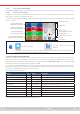
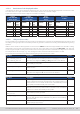
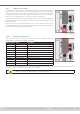
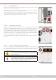
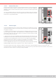
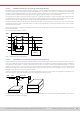
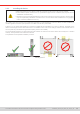
Table Of Contents
- 1. General
- 1.1 About this document
- 1.2 Warranty
- 1.3 Limitation of liability
- 1.4 Disposal of equipment
- 1.5 Product key
- 1.6 Intended usage
- 1.7 Safety
- 1.8 Technical Data
- 1.9 Construction and function
- 1.9.1 General description
- 1.9.2 Block diagram
- 1.9.3 Scope of delivery
- 1.9.4 Accessories
- 1.9.5 Options
- 1.9.6 The control panel (HMI)
- 1.9.7 USB port (rear side)
- 1.9.8 Interface module slot
- 1.9.9 Analog interface
- 1.9.10 “Share BUS” connector
- 1.9.11 “Sense” connector (remote sensing)
- 1.9.12 Master-Slave bus
- 1.9.13 Ethernet port
- 2. Installation & commissioning
- 2.1 Transport and storage
- 2.2 Unpacking and visual check
- 2.3 Installation
- 2.3.1 Safety procedures before installation and use
- 2.3.2 Preparation
- 2.3.3 Installing the device
- 2.3.4 Connection to AC supply
- 2.3.5 Connection to DC sources
- 2.3.6 Connection of remote sensing
- 2.3.7 Grounding of the DC terminal
- 2.3.8 Installation of an interface module
- 2.3.9 Connection of the analog interface
- 2.3.10 Connection of the Share bus
- 2.3.11 Connection of the USB port (rear side)
- 2.3.12 Initial commission
- 2.3.13 Commission after a firmware update or a long period of non-use
- 3. Operation and application
- 3.1 Important notes
- 3.2 Operating modes
- 3.3 Alarm conditions
- 3.4 Manual operation
- 3.5 Remote control
- 3.6 Alarms and monitoring
- 3.7 Locking the control panel (HMI)
- 3.8 Locking the adjustment limits and user profiles
- 3.9 Loading and saving user profiles
- 3.10 The function generator
- 3.10.1 Introduction
- 3.10.2 General
- 3.10.3 Method of operation
- 3.10.4 Manual operation
- 3.10.5 Sine wave function
- 3.10.6 Triangular function
- 3.10.7 Rectangular function
- 3.10.8 Trapezoidal function
- 3.10.9 DIN 40839 function
- 3.10.10 Arbitrary function
- 3.10.11 Ramp function
- 3.10.12 IU table function (XY table)
- 3.10.13 Battery test function
- 3.10.14 MPP tracking function
- 3.10.15 Remote control of the function generator
- 3.11 Other applications
- 4. Service and maintenance
- 5. Contact and support

© EA Elektro-Automatik in 2022, this information is subject to change without notice 2933200840_manual_elr_10000_2u_3kw_en_02
2.3.3 Installing the device
• Select the location for the device so that the connection to the source is as short as possible.
• Leave sucient space, at least 30 cm (1 ft), behind the equipment for ventilation (only required for the
standard air-cooled version)
• The device must not be operated without a proper touch protection for the AC connection, which is either
only accomplished by installation of the device in a 19” rack/cabinet with lockable doors or by applying
further measures (additional cover etc.)
All models in this series require to be installed and operated in a closed appliance, such as a cabinet. It’s also mandatory to
install a rigid AC connection. Open operation on a desk or similar isn’t permissible.
A device in a 19” chassis will usually be mounted on suitable rails and installed in 19” racks or cabinets. The depth of the
device and its weight must be taken into account. The handles on the front are for sliding in and out of the cabinet. Slots on
the front plate are provided for xing the device (xing screws not included).
The unacceptable positions, as shown below, are also valid for the vertical mount of the device onto a wall (room or inside a
cabinet). The required air ow would be insucient.
Acceptable and unacceptable installation positions:
Standing surface