
Manual
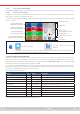
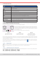
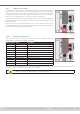
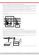
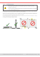
Table Of Contents
- 1. General
- 1.1 About this document
- 1.2 Warranty
- 1.3 Limitation of liability
- 1.4 Disposal of equipment
- 1.5 Product key
- 1.6 Intended usage
- 1.7 Safety
- 1.8 Technical Data
- 1.9 Construction and function
- 1.9.1 General description
- 1.9.2 Block diagram
- 1.9.3 Scope of delivery
- 1.9.4 Accessories
- 1.9.5 Options
- 1.9.6 The control panel (HMI)
- 1.9.7 USB port (rear side)
- 1.9.8 Interface module slot
- 1.9.9 Analog interface
- 1.9.10 “Share BUS” connector
- 1.9.11 “Sense” connector (remote sensing)
- 1.9.12 Master-Slave bus
- 1.9.13 Ethernet port
- 2. Installation & commissioning
- 2.1 Transport and storage
- 2.2 Unpacking and visual check
- 2.3 Installation
- 2.3.1 Safety procedures before installation and use
- 2.3.2 Preparation
- 2.3.3 Installing the device
- 2.3.4 Connection to AC supply
- 2.3.5 Connection to DC sources
- 2.3.6 Connection of remote sensing
- 2.3.7 Grounding of the DC terminal
- 2.3.8 Installation of an interface module
- 2.3.9 Connection of the analog interface
- 2.3.10 Connection of the Share bus
- 2.3.11 Connection of the USB port (rear side)
- 2.3.12 Initial commission
- 2.3.13 Commission after a firmware update or a long period of non-use
- 3. Operation and application
- 3.1 Important notes
- 3.2 Operating modes
- 3.3 Alarm conditions
- 3.4 Manual operation
- 3.5 Remote control
- 3.6 Alarms and monitoring
- 3.7 Locking the control panel (HMI)
- 3.8 Locking the adjustment limits and user profiles
- 3.9 Loading and saving user profiles
- 3.10 The function generator
- 3.10.1 Introduction
- 3.10.2 General
- 3.10.3 Method of operation
- 3.10.4 Manual operation
- 3.10.5 Sine wave function
- 3.10.6 Triangular function
- 3.10.7 Rectangular function
- 3.10.8 Trapezoidal function
- 3.10.9 DIN 40839 function
- 3.10.10 Arbitrary function
- 3.10.11 Ramp function
- 3.10.12 IU table function (XY table)
- 3.10.13 Battery test function
- 3.10.14 MPP tracking function
- 3.10.15 Remote control of the function generator
- 3.11 Other applications
- 4. Service and maintenance
- 5. Contact and support

© EA Elektro-Automatik in 2022, this information is subject to change without notice 2833200840_manual_elr_10000_2u_3kw_en_02
2.3.2.2 Additional measure for energy recovering devices
All models of this series are so-called recuperating devices. In this is mode they feed back a specic amount of energy into
the local or public grid. The devices can’t work at all without this functionality. The goal is to consume the recovered energy
completely in the local power grid of a company or plant. In case it can occur that more energy is recuperated than consumed,
the excess will be fed back into the public grid which usually isn’t allowed without further precautions.
The operator of the device must,owing to circumstances, contact the local electric utility and clarify what’s allowed and if a
so-called network & system protection is required to be installed. There are several different international provisions or stan-
dard, such as the german VDE-AR-N 4105/4110 or the british ENA EREC G99 which regulate this situation.
The device itself provides a basic protection and would shut down energy feed back in case it can’t work, but a full protec-
tion against frequency shift or voltage deviation can only be accomplished by such an NS protection device, which will also
prevent isolation operation.
We offer NS protection solutions. They already fulll the german AR-N 4105 and 4410, as well as the italian CEI 0-21 or the
british G59/G98/G99.
Concept of an NS protection system:
Su per vis io n
D ev ic e
L1
L2
L3
PE
N
GRID
Figure 9 - Principle of an NS protection network
2.3.2.3 Installation concept for energy recovering devices
An ELR 10000 device recovers energy and feeds it back into the local power grid of a company or big electric plant. The recov-
ered current adds to the grid current (see schematic below) and this can lead to an overload of the existing electric installation.
Considering any two outlets, no matter of what type they are, there is usually no extra fusing installed in between. In case of
a defect in the AC part (i.e. short-circuit) of any consumer device or when there are multiple devices connected which could
take a higher power, the total current could ow across wires which are not laid out for this higher current. It could lead to
damage or even re in the wires or connection points.
In order to avoid damages and accidents, the existing installation concept must be taken into regard before installing such
recovering devices. Schematic depiction with 1 recovering device and consumers:
PSB/ELR 10000 2U
<16 A
63 A
Gri d
Con sumer 2Con sumer 2
Con sumer 1Con sumer 1
up to 7 9 A
When running a higher number of recovering, i. e. energy backfeeding units on the same leg of the installation, the total cur-
rents per phase increases accordingly.