
Manual
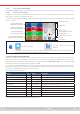
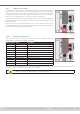
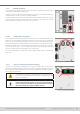
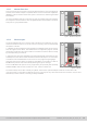
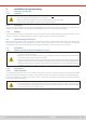
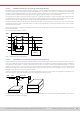
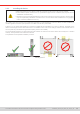
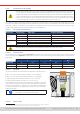
Table Of Contents
- 1. General
- 1.1 About this document
- 1.2 Warranty
- 1.3 Limitation of liability
- 1.4 Disposal of equipment
- 1.5 Product key
- 1.6 Intended usage
- 1.7 Safety
- 1.8 Technical Data
- 1.9 Construction and function
- 1.9.1 General description
- 1.9.2 Block diagram
- 1.9.3 Scope of delivery
- 1.9.4 Accessories
- 1.9.5 Options
- 1.9.6 The control panel (HMI)
- 1.9.7 USB port (rear side)
- 1.9.8 Interface module slot
- 1.9.9 Analog interface
- 1.9.10 “Share BUS” connector
- 1.9.11 “Sense” connector (remote sensing)
- 1.9.12 Master-Slave bus
- 1.9.13 Ethernet port
- 2. Installation & commissioning
- 2.1 Transport and storage
- 2.2 Unpacking and visual check
- 2.3 Installation
- 2.3.1 Safety procedures before installation and use
- 2.3.2 Preparation
- 2.3.3 Installing the device
- 2.3.4 Connection to AC supply
- 2.3.5 Connection to DC sources
- 2.3.6 Connection of remote sensing
- 2.3.7 Grounding of the DC terminal
- 2.3.8 Installation of an interface module
- 2.3.9 Connection of the analog interface
- 2.3.10 Connection of the Share bus
- 2.3.11 Connection of the USB port (rear side)
- 2.3.12 Initial commission
- 2.3.13 Commission after a firmware update or a long period of non-use
- 3. Operation and application
- 3.1 Important notes
- 3.2 Operating modes
- 3.3 Alarm conditions
- 3.4 Manual operation
- 3.5 Remote control
- 3.6 Alarms and monitoring
- 3.7 Locking the control panel (HMI)
- 3.8 Locking the adjustment limits and user profiles
- 3.9 Loading and saving user profiles
- 3.10 The function generator
- 3.10.1 Introduction
- 3.10.2 General
- 3.10.3 Method of operation
- 3.10.4 Manual operation
- 3.10.5 Sine wave function
- 3.10.6 Triangular function
- 3.10.7 Rectangular function
- 3.10.8 Trapezoidal function
- 3.10.9 DIN 40839 function
- 3.10.10 Arbitrary function
- 3.10.11 Ramp function
- 3.10.12 IU table function (XY table)
- 3.10.13 Battery test function
- 3.10.14 MPP tracking function
- 3.10.15 Remote control of the function generator
- 3.11 Other applications
- 4. Service and maintenance
- 5. Contact and support

© EA Elektro-Automatik in 2022, this information is subject to change without notice 2733200840_manual_elr_10000_2u_3kw_en_02
2. Installation & commissioning
2 .1 Transport and storage
2 .1.1 Transpor t
• The handles on the front and rear side of the device are not for carrying!
• Do not transport when switched on or connected!
• When relocating the equipment use of the original packing is recommended
• The device should always be carried and mounted horizontally
2 .1.2 Packaging
It’s recommended to keep the complete transport packaging for the lifetime of the device for relocation or return to the man-
ufacturer for repair. Otherwise the packaging should be disposed of in an environmentally friendly way.
2 .1.3 Storage
In case of long term storage of the equipment it’s recommended to use the original packaging or similar. Storage must be in
dry rooms, if possible in sealed packaging, to avoid corrosion, especially internal, through humidity.
2.2 Unpacking and visual check
After every transport, with or without packaging, or before commissioning, the equipment should be visually inspected for
damage and completeness using the delivery note and/or parts list (see section
“1.9.3. Scope of delivery”
). An obviously
damaged device (e.g. loose parts inside, damage outside) must under no circumstances be put in operation.
2.3 Installation
2.3.1 Safety procedures before installation and use
• When using a 19” rack, rails suitable for the width of the housing and the weight of the device are to be
used (see
“1.8. Technical Data”
• Before connecting to the mains ensure the supply voltage is as shown on the product label. Overvoltage
on the AC supply can cause equipment damage.
• Devices of this series feature an energy recovery function which, similar to solar energy equipment, which
feeds energy back into the local or public grid. Feedback into the public grid must not be operated without
adherence of directives from the local energy supplying company and it must be investigated before the
installation or latest before initial commission if there is requirement to install a grid protection device!
2.3.2 Preparation
2.3.2.1 Selecting cables
The required AC supply connection for these device is termination. It’s done via the 3 pole clamp terminal on the rear (AC lter
box). Wiring of the terminal requires a 3 wire (L, N, PE) cable of suitable cross section and length (not included in delivery).
For recommendations for a cable cross section see
“2.3.4. Connection to AC supply”.
Dimensioning of the DC wiring to the
source has to reect the following:
• The cable cross section should always be specied for at least the maximum current of the device.
• Continuous operation at the approved limit generates heat which must be removed, as well as voltage
loss which depends on cable length and heating. To compensate for these the cable cross section should
be increased and the cable length reduced.