
Manual
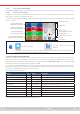
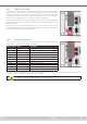
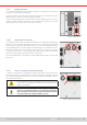
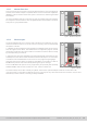
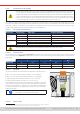
Table Of Contents
- 1. General
- 1.1 About this document
- 1.2 Warranty
- 1.3 Limitation of liability
- 1.4 Disposal of equipment
- 1.5 Product key
- 1.6 Intended usage
- 1.7 Safety
- 1.8 Technical Data
- 1.9 Construction and function
- 1.9.1 General description
- 1.9.2 Block diagram
- 1.9.3 Scope of delivery
- 1.9.4 Accessories
- 1.9.5 Options
- 1.9.6 The control panel (HMI)
- 1.9.7 USB port (rear side)
- 1.9.8 Interface module slot
- 1.9.9 Analog interface
- 1.9.10 “Share BUS” connector
- 1.9.11 “Sense” connector (remote sensing)
- 1.9.12 Master-Slave bus
- 1.9.13 Ethernet port
- 2. Installation & commissioning
- 2.1 Transport and storage
- 2.2 Unpacking and visual check
- 2.3 Installation
- 2.3.1 Safety procedures before installation and use
- 2.3.2 Preparation
- 2.3.3 Installing the device
- 2.3.4 Connection to AC supply
- 2.3.5 Connection to DC sources
- 2.3.6 Connection of remote sensing
- 2.3.7 Grounding of the DC terminal
- 2.3.8 Installation of an interface module
- 2.3.9 Connection of the analog interface
- 2.3.10 Connection of the Share bus
- 2.3.11 Connection of the USB port (rear side)
- 2.3.12 Initial commission
- 2.3.13 Commission after a firmware update or a long period of non-use
- 3. Operation and application
- 3.1 Important notes
- 3.2 Operating modes
- 3.3 Alarm conditions
- 3.4 Manual operation
- 3.5 Remote control
- 3.6 Alarms and monitoring
- 3.7 Locking the control panel (HMI)
- 3.8 Locking the adjustment limits and user profiles
- 3.9 Loading and saving user profiles
- 3.10 The function generator
- 3.10.1 Introduction
- 3.10.2 General
- 3.10.3 Method of operation
- 3.10.4 Manual operation
- 3.10.5 Sine wave function
- 3.10.6 Triangular function
- 3.10.7 Rectangular function
- 3.10.8 Trapezoidal function
- 3.10.9 DIN 40839 function
- 3.10.10 Arbitrary function
- 3.10.11 Ramp function
- 3.10.12 IU table function (XY table)
- 3.10.13 Battery test function
- 3.10.14 MPP tracking function
- 3.10.15 Remote control of the function generator
- 3.11 Other applications
- 4. Service and maintenance
- 5. Contact and support

© EA Elektro-Automatik in 2022, this information is subject to change without notice 2633200840_manual_elr_10000_2u_3kw_en_02
1.9 .12 Master-Slave bus
There is a further set of connectors on the rear side of the device, comprising two RJ45
sockets, which enables multiple compatible devices to be connected via a digital bus
(RS485) in order to create a master-slave system. Connection is made using standard
CAT5 cables.
It’s recommended to keep the connections as short as possible and to terminate the
bus if required. The termination is done via digital switches and activated in the device
setup menu in group “Master-Slave”.
Figure 7 - Master slave bus ports
1.9 .13 Ethernet port
The RJ45 LAN/Ethernet port on the rear side of the device is provided for communi-
cation with the device in terms of remote control or monitoring. The user has basically
two options of access:
1. A website (HTTP, port 80) which is accessible in a standard browser via the IP or the
host name given for the device. This website offers a conguration page for network
parameters, as well as an input box for SCPI commands to control the device remotely
by manually entering commands.
2. TCP/IP access via a freely selectable port (except 80 and other reserved ports). The
standard port for this device is 5025. Via TCP/IP and the selected port, communication
to the device can be established in most of the common programming languages.
Using this LAN port, the device can either be controlled by commands from SCPI or
ModBus RTU protocol, while automatically detecting the type of message.
Access via ModBus TCP protocol is only supported by the optionally and separately
available ModBus TCP interface module. See
”1.9.8. Interface module slot”.
Figure 8 - LAN port
The network setup can be done manually or by DHCP. Transmission speed and duplex mode are on automatic mode.
If remote control is in operation the Ethernet port has no priority over any other interface and can, therefore, only be used
alternatively to these. However, monitoring is always available.