
Manual
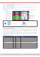
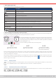
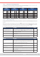
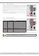
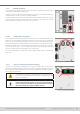
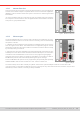
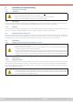
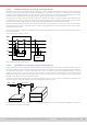
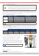
Table Of Contents
- 1. General
- 1.1 About this document
- 1.2 Warranty
- 1.3 Limitation of liability
- 1.4 Disposal of equipment
- 1.5 Product key
- 1.6 Intended usage
- 1.7 Safety
- 1.8 Technical Data
- 1.9 Construction and function
- 1.9.1 General description
- 1.9.2 Block diagram
- 1.9.3 Scope of delivery
- 1.9.4 Accessories
- 1.9.5 Options
- 1.9.6 The control panel (HMI)
- 1.9.7 USB port (rear side)
- 1.9.8 Interface module slot
- 1.9.9 Analog interface
- 1.9.10 “Share BUS” connector
- 1.9.11 “Sense” connector (remote sensing)
- 1.9.12 Master-Slave bus
- 1.9.13 Ethernet port
- 2. Installation & commissioning
- 2.1 Transport and storage
- 2.2 Unpacking and visual check
- 2.3 Installation
- 2.3.1 Safety procedures before installation and use
- 2.3.2 Preparation
- 2.3.3 Installing the device
- 2.3.4 Connection to AC supply
- 2.3.5 Connection to DC sources
- 2.3.6 Connection of remote sensing
- 2.3.7 Grounding of the DC terminal
- 2.3.8 Installation of an interface module
- 2.3.9 Connection of the analog interface
- 2.3.10 Connection of the Share bus
- 2.3.11 Connection of the USB port (rear side)
- 2.3.12 Initial commission
- 2.3.13 Commission after a firmware update or a long period of non-use
- 3. Operation and application
- 3.1 Important notes
- 3.2 Operating modes
- 3.3 Alarm conditions
- 3.4 Manual operation
- 3.5 Remote control
- 3.6 Alarms and monitoring
- 3.7 Locking the control panel (HMI)
- 3.8 Locking the adjustment limits and user profiles
- 3.9 Loading and saving user profiles
- 3.10 The function generator
- 3.10.1 Introduction
- 3.10.2 General
- 3.10.3 Method of operation
- 3.10.4 Manual operation
- 3.10.5 Sine wave function
- 3.10.6 Triangular function
- 3.10.7 Rectangular function
- 3.10.8 Trapezoidal function
- 3.10.9 DIN 40839 function
- 3.10.10 Arbitrary function
- 3.10.11 Ramp function
- 3.10.12 IU table function (XY table)
- 3.10.13 Battery test function
- 3.10.14 MPP tracking function
- 3.10.15 Remote control of the function generator
- 3.11 Other applications
- 4. Service and maintenance
- 5. Contact and support

© EA Elektro-Automatik in 2022, this information is subject to change without notice 2533200840_manual_elr_10000_2u_3kw_en_02
1.9.9 Analog interface
This 15 pole D-sub socket on the rear side of the device is provided for remote control
of the device via analog or digital signals.
If remote control is in operation this analog interface can only be used alternately to the
digital interface. However, monitoring is always available.
The input voltage range of the set values and the output voltage range of the monitor
values, as well as reference voltage level can be switched in the settings menu of the
device between 0-5 V and 0-10 V, in each case for 0-100%.
Figure 4 - Analog interface
1.9 .10 “Share BUS” connector
The two BNC sockets (50 Ω type) labeled “Share BUS” form a digital, passed-through
Share bus. This bus is bidirectional and connects the bus master unit via “Share BUS
Output” to the next slave unit (“Share BUS Input”) etc., for use in parallel operation (mas-
ter-slave). BNC cables of suitable length can be obtained from us or electronics stores.
Basically, all 10000 series are compatible on this Share bus, though only connection
of the same device type, i. e. power supply with power supply or electronic load with
electronic load is supported by the devices for master-slave.
For an ELR 10000 device only different or identical ELR 10000 models can be used as
slave units.
Figure 5 - Share bus
1.9 .11 “Sense” connector (remote sensing)
In order to compensate for voltage drops along the DC cables external source, the
Sense input (2 plugs included in delivery, one each for positive and negative pole) can
be connected to the external source. The maximum possible compensation is given in
the technical specications.
In a master-slave system it’s intended to wire remote sensing only
to the master which would then forward the compensation to the
slaves via Share BUS.
The Sense cover must be installed during operation, because
there can be hazardous voltage on the sense lines! Recongu-
ration on the Sense terminals is only permissible if the device is
disconnected from AC supply and all DC sources!
Figure 6 - Remote sensing terminals