
Manual
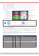
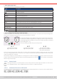
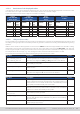
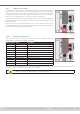
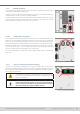
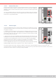
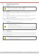
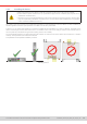
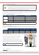
Table Of Contents
- 1. General
- 1.1 About this document
- 1.2 Warranty
- 1.3 Limitation of liability
- 1.4 Disposal of equipment
- 1.5 Product key
- 1.6 Intended usage
- 1.7 Safety
- 1.8 Technical Data
- 1.9 Construction and function
- 1.9.1 General description
- 1.9.2 Block diagram
- 1.9.3 Scope of delivery
- 1.9.4 Accessories
- 1.9.5 Options
- 1.9.6 The control panel (HMI)
- 1.9.7 USB port (rear side)
- 1.9.8 Interface module slot
- 1.9.9 Analog interface
- 1.9.10 “Share BUS” connector
- 1.9.11 “Sense” connector (remote sensing)
- 1.9.12 Master-Slave bus
- 1.9.13 Ethernet port
- 2. Installation & commissioning
- 2.1 Transport and storage
- 2.2 Unpacking and visual check
- 2.3 Installation
- 2.3.1 Safety procedures before installation and use
- 2.3.2 Preparation
- 2.3.3 Installing the device
- 2.3.4 Connection to AC supply
- 2.3.5 Connection to DC sources
- 2.3.6 Connection of remote sensing
- 2.3.7 Grounding of the DC terminal
- 2.3.8 Installation of an interface module
- 2.3.9 Connection of the analog interface
- 2.3.10 Connection of the Share bus
- 2.3.11 Connection of the USB port (rear side)
- 2.3.12 Initial commission
- 2.3.13 Commission after a firmware update or a long period of non-use
- 3. Operation and application
- 3.1 Important notes
- 3.2 Operating modes
- 3.3 Alarm conditions
- 3.4 Manual operation
- 3.5 Remote control
- 3.6 Alarms and monitoring
- 3.7 Locking the control panel (HMI)
- 3.8 Locking the adjustment limits and user profiles
- 3.9 Loading and saving user profiles
- 3.10 The function generator
- 3.10.1 Introduction
- 3.10.2 General
- 3.10.3 Method of operation
- 3.10.4 Manual operation
- 3.10.5 Sine wave function
- 3.10.6 Triangular function
- 3.10.7 Rectangular function
- 3.10.8 Trapezoidal function
- 3.10.9 DIN 40839 function
- 3.10.10 Arbitrary function
- 3.10.11 Ramp function
- 3.10.12 IU table function (XY table)
- 3.10.13 Battery test function
- 3.10.14 MPP tracking function
- 3.10.15 Remote control of the function generator
- 3.11 Other applications
- 4. Service and maintenance
- 5. Contact and support

© EA Elektro-Automatik in 2022, this information is subject to change without notice 2433200840_manual_elr_10000_2u_3kw_en_02
1.9.7 USB port (rear side)
The USB port on the rear side of the device is provided for communication with the
device and for rmware updates. The included USB cable can be used to connect the
device to a PC (USB 2.0 or 3.0). The driver is delivered with the device and installs a
virtual COM port. Details about remote control can be found in form of a programming
guide on the included USB stick or on the web site of the manufacturer.
The device can be addressed via this port either using the international standard Mod-
Bus RTU protocol or by SCPI language. The device recognizes the message protocol
used automatically.
If remote control is in operation the USB port has no priority over either the interface
module (see below) or the analog interface and can, therefore, only be used alternatively
to these. However, monitoring is always available.
Figure 2 - USB port
1.9.8 Interface module slot
This slot on the rear side of the device is can receive various modules of the IF-AB
interface series. The following options are available:
Figure 3 - Interface slot
Article number Name Description
35400100 IF-AB-CANO CANopen, 1x DB9, male
35400101 IF-AB-RS232
RS 232, 1x DB9, male (null modem)
35400103 IF-AB-PBUS Probus DP-V1 Slave, 1x DB9, female
35400104 IF-AB-ETH1P Ethernet, 1x RJ45
35400105 IF-AB-PNET1P ProNET IO, 1x RJ45
35400107 IF-AB-MBUS1P ModBus TCP, 1x RJ45
35400108 IF-AB-ETH2P Ethernet, 2x RJ45
35400109 IF-AB-MBUS2P ModBus TCP, 2x RJ45
35400110 IF-AB-PNET2P ProNET IO, 2x RJ45
35400111 IF-AB-CAN CAN 2.0 A / 2.0 B, 1x DB9, male
35400112 IF-AB-ECT EtherCAT, 1x RJ45
The modules can be installed by the user and hence retrotted without problem. A rmware update of the device may be
necessary in order to recognize and support certain modules.
Switch your device off before adding or removing modules!